
 Huanghua Group Co., Ltd.
Power Pole Transformer: How It Works, Main Parts and Selection Checks
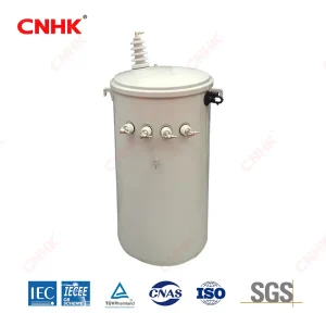
A power pole transformer is a distribution transformer supported on a utility pole or a suitable pole structure. It changes the distribution voltage to the voltage required by the downstream supply. The familiar cylindrical tank is only the visible enclosure; the core, windings and insulating system perform the electrical transformation inside.
Pole mounting describes where the equipment is supported. It does not establish a universal voltage, capacity, number of bushings or secondary connection. Those details depend on the network and the selected transformer.
Where it sits in the supply route
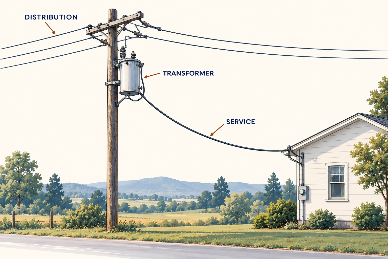
An overhead distribution circuit carries power through the local network. A distribution transformer supplies the required downstream voltage, and the service connection carries that supply toward the customer. The transformer is one part of the route, alongside conductors, protection, switching and the network’s earthing arrangement.
For a new connection or replacement, identify the actual network configuration before selecting equipment. A residential-looking installation in one country is not a reliable specification for another utility’s system.
Main parts and their roles
| Part | Role | What a buyer should confirm |
|---|---|---|
| Core and windings | Provide magnetic coupling and the voltage relationship. | Rated winding voltages, capacity and connection. |
| Tank and insulating liquid | House the active assembly and form part of its insulation and thermal design. | Construction, fluid specification and service conditions. |
| Bushings and terminals | Provide insulated electrical interfaces through the enclosure. | Arrangement and compatibility with the specified connections. |
| Mounting provisions | Connect the transformer mechanically to its support. | Outline, mass and mounting details. |
| Nameplate | Identifies the unit and its rated information. | Agreement with the purchase specification and drawings. |
Accessories and protective devices vary. A surge arrester, fuse or other protection component visible near a transformer may belong to the wider installation rather than to the transformer as supplied. Specify the supply boundary explicitly.
What changes inside the pole-mounted tank?
Alternating current in the primary winding establishes changing magnetic flux in the core. That flux links the secondary winding and induces its voltage. The winding turns relationship sets the approximate voltage transformation; the tank and mounting bracket do not determine the electrical ratio.
For a simplified example, suppose a transformer is specified at 7,200 V to 240 V and 25 kVA. Its nominal voltage ratio is 30:1. The corresponding single-phase rated-current calculation gives about 3.47 A at 7,200 V and 104.2 A at 240 V. These are hypothetical teaching values, not a universal utility arrangement or a Huanghua model specification.
The example explains why the secondary carries more current at lower voltage. It does not define a service connection: whether a center tap is present, how terminals are identified, and what grounding arrangement is used must come from the actual utility design. A 240 V label alone does not identify all of those details.
The insulating liquid contributes to insulation and heat transfer within the specified design. Bushings provide insulated paths through the tank wall. The external protection and service conductors complete other parts of the distribution system; they should not all be mistaken for components supplied inside the transformer tank.
Voltage and capacity are separate checks
The winding voltages must fit the supply and the required service arrangement. The kVA requirement follows the assessed load duty. A replacement that matches only the tank size, or only the kVA marking, may leave the connection or voltage requirement unresolved.
Ask for the selected tap arrangement and its operating limitations where taps are provided. A tap label is not permission to alter the unit while energized. The project should retain the actual connection drawing and manufacturer instructions with the equipment records.
Mounting and access belong in the enquiry
Provide the proposed support arrangement, dimensional constraints and utility requirements to the responsible designer. The transformer supplier can supply equipment mass and mounting details; the suitability of the pole and installation is a separate engineering question.
What the Huanghua product route covers
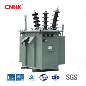
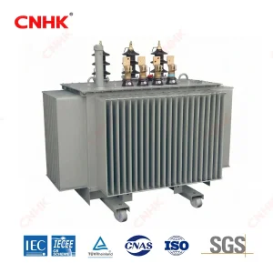
Huanghua’s single-phase oil-immersed distribution transformer is described for pole mounting and utility distribution duties. The published product description includes a tank, mounting provisions and bushing arrangements, making it a relevant starting point for this type of enquiry.
Request the exact offered configuration and its documents. Do not infer a local utility approval, an included external protection package or a particular secondary connection from the generic product photograph.
Information that makes replacement enquiries useful
Send a legible nameplate record, the existing connection and outline drawings, the service requirement, and the reason for replacement. Record whether the project involves a like-for-like equipment change or a network/load change. The latter can require a different assessment even if the old transformer operated satisfactorily.
If the equipment is damaged or making unusual noises, keep the public away and contact the utility or site operator. Identification for procurement should come from available records and authorized personnel, not an attempt to approach or inspect energized pole equipment.