
 Huanghua Group Co., Ltd.
Single Phase Transformer: Working Principle, Types and Rating Checks
A single phase transformer transfers electrical energy between circuits through a changing magnetic field associated with one AC phase. Its winding arrangement establishes the voltage relationship, while its rated capacity and service conditions determine the duty for which it is designed.
The phrase describes the electrical configuration. It does not automatically mean a small indoor transformer: single-phase distribution transformers can also serve overhead utility networks and other specified loads.
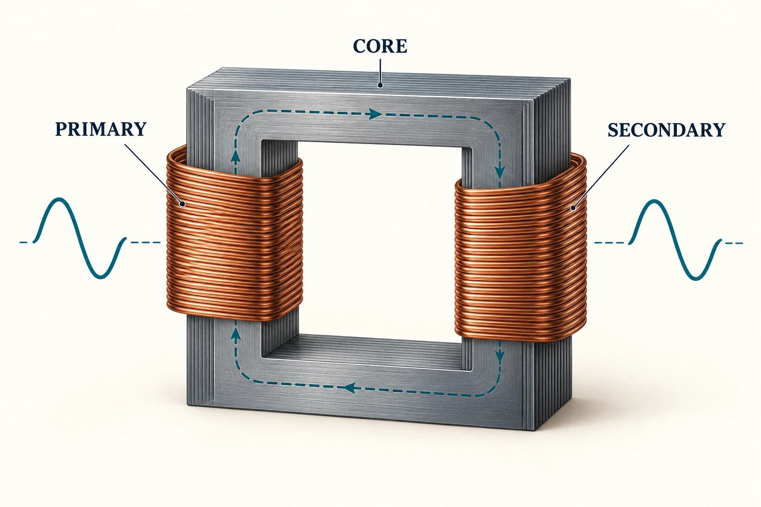
Primary, core and secondary
The energized primary winding produces alternating magnetic flux in the core. That changing flux links the secondary winding and induces voltage. For an ideal transformer, the ratio of winding voltages follows the ratio of turns. A real transformer also has losses and voltage drop under load.
The transformer does not convert the supply frequency into a new frequency. The proposed design must be appropriate for the stated supply. Supplying a different frequency or voltage is not a harmless catalog substitution.
Voltage ratio and kVA describe different requirements
Voltage ratio establishes the relationship required between the two sides. The kVA rating describes apparent-power capacity under specified conditions. Two units can provide the same voltage transformation while having very different capacities, dimensions and installation requirements.
For a single-phase circuit, apparent power in VA is the RMS voltage multiplied by RMS current. Dividing by 1,000 expresses the result in kVA. This relationship helps check units; it does not replace a load assessment that considers starting duty, load variation and the manufacturer’s service conditions.
For example, a quotation that states only a primary and secondary voltage leaves the load duty unanswered. A quotation that states only kVA leaves the winding voltages unanswered. Both must be resolved before the product can be meaningfully compared with another offer.
A voltage-ratio and kVA example
Take an idealized 10 kVA single-phase transformer with a 400 V primary and a 200 V secondary. The nominal voltage ratio is 400 / 200 = 2:1. At the stated apparent-power rating, the corresponding currents are 10,000 / 400 = 25 A on the primary and 10,000 / 200 = 50 A on the secondary.
The example shows why a lower output voltage can accompany a higher output current without creating energy. Both sides represent 10 kVA in the idealized calculation. Actual input power includes losses, and secondary voltage varies with the specified regulation and loading conditions. These numbers illustrate relationships; they are not cable sizes, protection settings or the ratings of a named product.
The turns relationship is V1 / V2 ≈ N1 / N2 under the ideal-transformer approximation. It does not determine frequency conversion or establish that a transformer designed for one supply frequency can be used on another.
Single-phase transformer types
| Description | What changes | What remains to be specified |
|---|---|---|
| Step-up or step-down | The intended voltage relationship. | Both winding voltages and the rated duty. |
| Two-winding isolation | Separate input and output windings. | Voltage ratio, insulation and application requirements. |
| Autotransformer | A shared winding section; no galvanic isolation. | Whether this connection principle is permitted for the application. |
| Single secondary or split-secondary arrangement | The available secondary winding/terminal arrangement. | The exact connection schedule and rating of each permitted arrangement. |
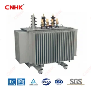
| Dry-type or liquid-filled | Insulation and thermal construction. | Installation, environment and service conditions. |
Can a single-phase transformer produce three-phase power?
An ordinary transformer supplied from a single-phase source does not create a balanced three-phase supply. Three-phase power requires the appropriate phase relationships; changing the turns ratio does not create them. A phase-conversion system is a different equipment task.
A bank of single-phase transformers can be used in an engineered three-phase system when supplied and connected appropriately. That is not the same as powering an ordinary single-phase transformer from one phase and obtaining three-phase power. Keeping the source, transformer bank and required load phases explicit prevents these descriptions from being confused.
Do not infer connections from the name
Single-phase equipment may have different winding and terminal arrangements, including split secondary arrangements in designs intended for that duty. Terminal identification, polarity and any tap provisions must come from the exact nameplate and connection drawing.
A familiar-looking tank is not evidence of a familiar connection. Even when two drawings use similar terminal letters, the complete diagram and its notes determine what those letters mean for that unit. Keep the drawing revision and transformer serial number together in project records.
Questions that distinguish distribution proposals
| Enquiry field | Useful information |
|---|---|
| Electrical system | Primary voltage, secondary voltage, frequency and required connection arrangement. |
| Load | Required capacity, expected load profile and any important starting duty. |
| Installation | Mounting arrangement, available space, access and cable or overhead interfaces. |
| Environment | Ambient conditions, altitude and exposure relevant to the site. |
| Documentation | Nameplate schedule, outline drawing, connection drawing and agreed test records. |
Where a pole-mounted oil-immersed unit fits
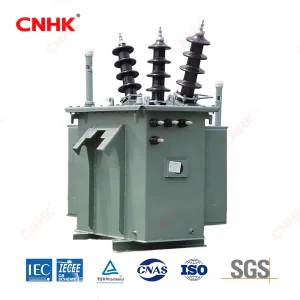
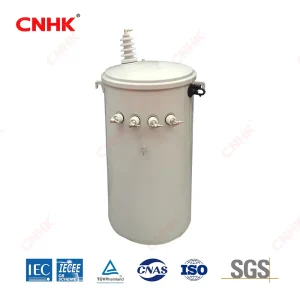
Huanghua’s single-phase oil-immersed distribution transformer is described for pole mounting and distribution applications. That makes it relevant when the enquiry calls for this combination of phase, construction and mounting.
The product route does not confirm the utility’s acceptance requirements, the capacity of an existing pole or compatibility with a particular network connection. Those interfaces should be defined in the project specification and checked against the offered configuration.