
 Huanghua Group Co., Ltd.




Lock Out Relay: What ANSI 86 Does in a Protection System
A lock out relay, commonly identified by the device function number 86, holds a protection-related trip or lockout condition until the specified reset action occurs. In an engineered scheme it can operate several contacts to trip equipment, block closing and provide indication. It is not normally the device that independently decides whether a transformer or busbar fault exists.
The distinction is important: the protection element detects a condition; the lockout function preserves and distributes the required response. The actual inputs, outputs and reset conditions belong to the project’s protection drawings.
What ANSI 86 contributes to the protection chain
A protective relay can issue an operating command when its configured criteria are met. A lockout relay can then latch the resulting state and use multiple contacts for the required actions. Manufacturer auxiliary-relay families include different reset arrangements, so “86” does not identify one universal physical device or reset mechanism.
A mechanical indication may show whether a particular relay is tripped or reset. That indication is useful evidence of state, but it does not explain the initiating cause. Event records, protection targets and the circuit drawings provide that context.
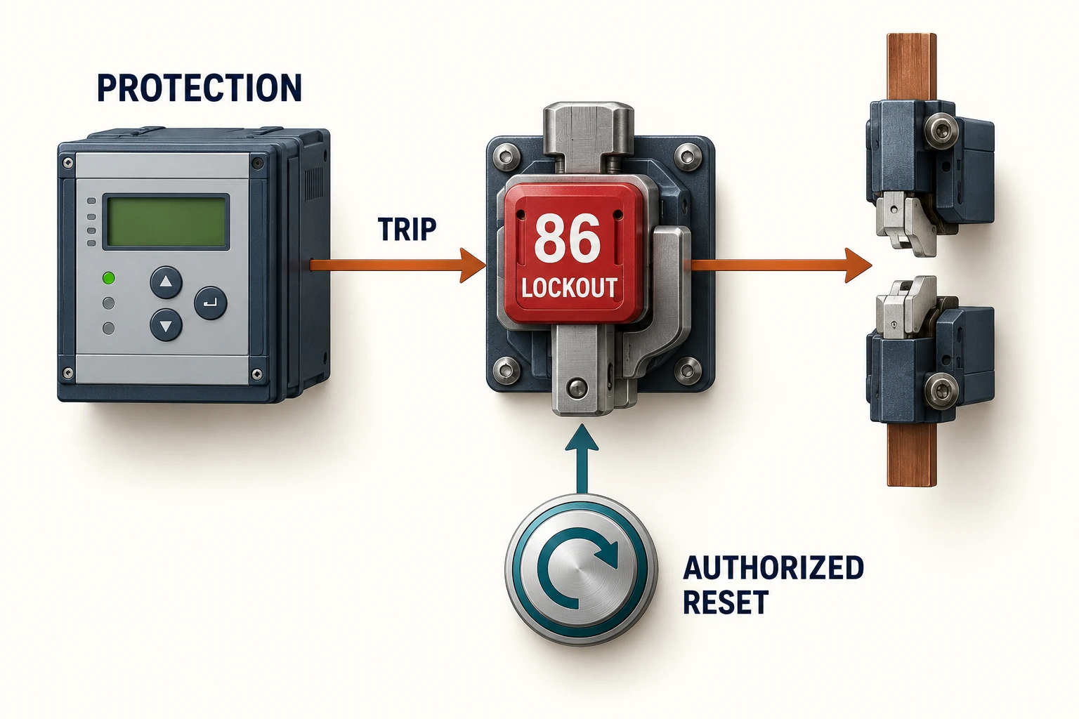
Trip, close blocking and alarm are separate outputs
| Output purpose | Project question |
|---|---|
| Trip | Which breaker or breakers must receive an opening command? |
| Close blocking | Which closing paths must remain inhibited while lockout is active? |
| Indication | Where is the state shown locally and remotely? |
| Reset | Who may authorize it, and what conditions must be satisfied? |
This table is a useful way to review an enquiry because a phrase such as “provide lockout” leaves several behaviors undefined. The same number of contacts does not prove that two proposals implement the same protection philosophy.
Reset does not prove that the fault has cleared
Reset changes the lockout state. It does not repair insulation, remove a failed component or establish that the plant is ready for energization. The investigation and release-to-service decision must remain distinct from operating the relay’s reset function.
For an operating procedure, identify the evidence that must be reviewed and the person responsible for authorization. Depending on the event, this may involve protection records, inspection findings and equipment test results. Do not replace that decision with an instruction to reset whenever the indication appears.
Specify the relay and the logic together
The hardware enquiry should cover control supply, reset arrangement, contact requirements and the duty each contact must switch. The logic enquiry should define initiating conditions, affected equipment, close-blocking paths and indication. Neither document is complete without the other.
Ask the supplier to identify how the relay is represented on the schematic and terminal schedule. If the proposal uses a numerical protection device to implement some lockout behavior, make that distinction explicit rather than assuming it reproduces every feature of a separate electromechanical relay.
Switchgear integration is project-specific
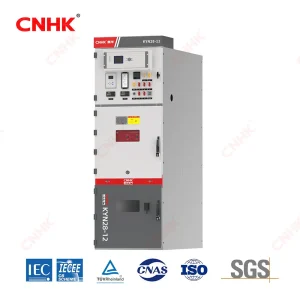
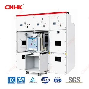
Huanghua’s KYN28 switchgear description includes a low-voltage compartment for specified protection and metering interfaces. This provides a place to discuss the required protection scheme; it does not mean every standard panel includes an ANSI 86 relay.
Supply the approved protection philosophy and cause-and-effect schedule with the switchgear enquiry. Request the proposed relay list, control drawings and terminal interfaces together. A useful review checks whether every intended initiating condition reaches the correct outputs and whether the stated reset behavior matches the operating policy.
Record the complete functional result
The agreed test record should identify the simulated input, observed trip outputs, close-blocking behavior, indications and reset outcome. A note that says only “relay operates” leaves the rest of the scheme unverified.
Keep the final settings, drawings and test records under the same revision control as the panel documentation. Later changes to a breaker, protection input or remote control can alter the scheme even when the lockout relay itself has not changed.