
 Huanghua Group Co., Ltd.
Earthing Arrangements Explained: TT, TN-S, TN-C-S and IT Systems
Earthing arrangements describe the relationship between the electrical source, earth and the exposed conductive parts of an installation. TT, TN-S, TN-C-S and IT are system descriptions. They help explain the protective arrangement; they are not instructions to connect a neutral conductor to any convenient earth terminal.
To read an arrangement correctly, identify the source first, then the protective-conductor route and the point at which any combined conductor separates. The protection design and the applicable local requirements must be considered with that drawing.
What the letters tell you
The first letter describes the source’s relationship to earth: T indicates a direct connection, while I indicates isolation from earth or a connection through impedance. The second letter describes how exposed conductive parts relate to earth or the earthed source point. Additional S and C designations distinguish separate and combined neutral/protective functions.
| Arrangement | Conceptual distinction |
|---|---|
| TT | The source has an earth connection; installation exposed conductive parts connect to an installation earth electrode. |
| TN-S | Neutral and protective conductors are separate. |
| TN-C-S | A combined protective-and-neutral function exists in one part, with separate functions downstream of the defined separation. |
| IT | The source is isolated from earth or connected through impedance; exposed conductive parts are earthed. |
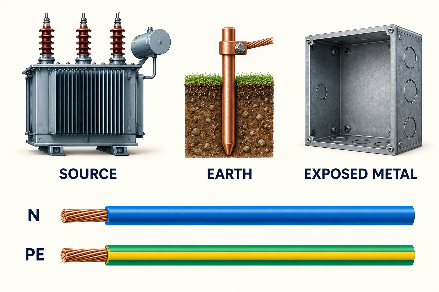
N, PE and PEN are different functions
N denotes neutral, PE denotes the protective conductor, and PEN combines protective and neutral functions. A conductor’s role follows the system design; it should not be identified from color or a photograph alone.
For a drawing review, ask where each function begins and ends. In a TN-C-S arrangement, the separation point is a critical piece of information. A simplified single-line diagram that omits it may be insufficient for approving the switchboard interface.
Trace the earth-fault return path
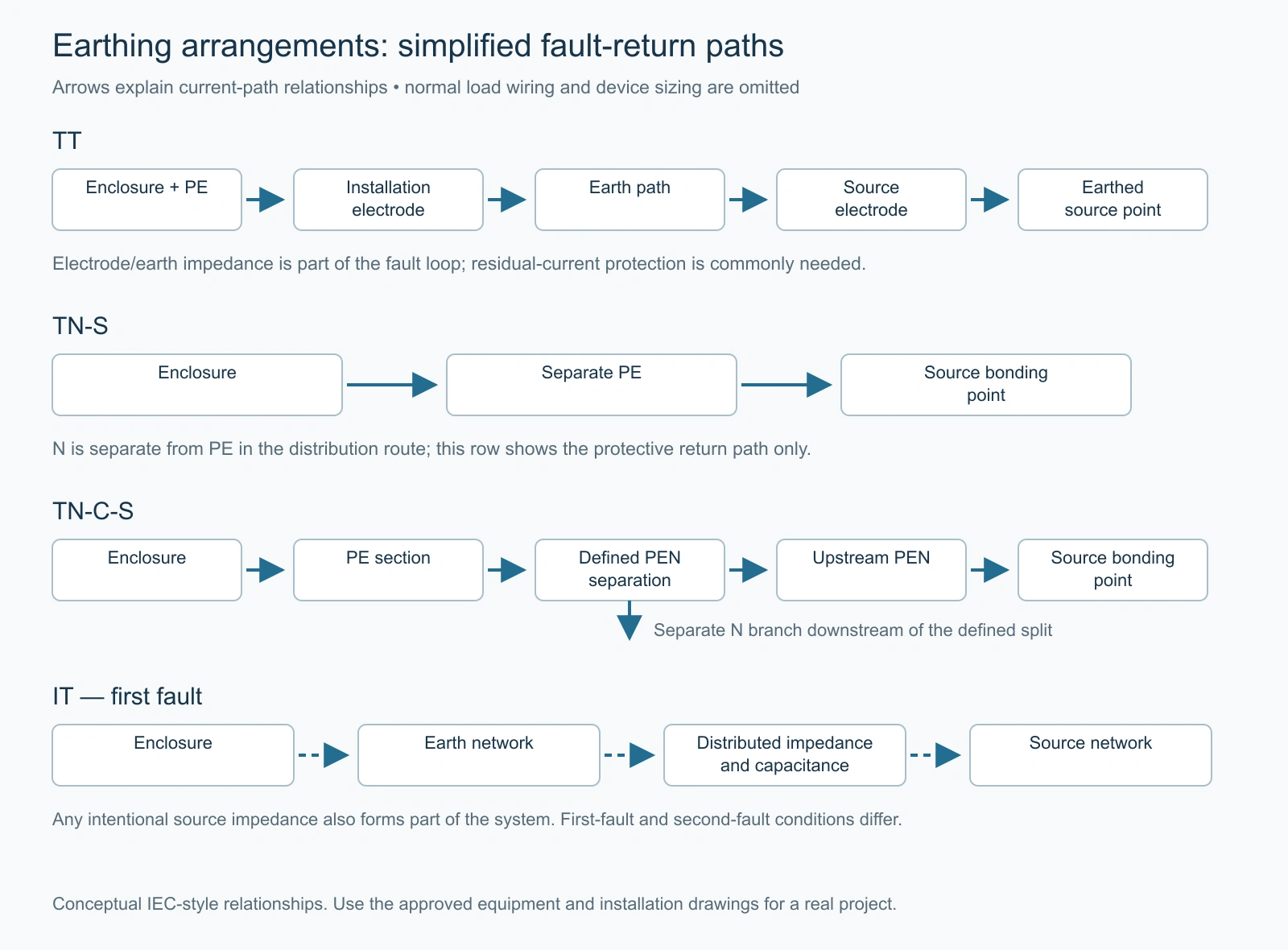
The following illustration compares simplified return paths for a fault from a live conductor to an exposed metal enclosure. It omits normal load wiring and device selection. Read it as an explanation of system behavior, not as a terminal connection drawing.
| System | Conceptual return route | Important consequence |
|---|---|---|
| TT | Enclosure → protective conductor → installation electrode → earth → source electrode and earthed source point. | The earth-electrode path can limit current. Fault protection commonly relies on residual-current devices rather than assuming an overcurrent device will clear every earth fault. |
| TN-S | Enclosure → separate PE conductor → source bonding point. | The protective path is separate from the neutral conductor; fault-loop conditions and protective-device operation must be coordinated. |
| TN-C-S | Enclosure → PE section → defined separation point → upstream PEN path → source. | The combined upstream conductor and its separation point are essential parts of the system description. |
| IT, first fault | Enclosure → earth network → the system’s distributed impedance/capacitance and any intentional source impedance. | There is no assumed solidly earthed neutral return. Monitoring and the response to a first fault are part of the protection design. |
For an IT system, a first fault and a second fault are different design conditions. A low first-fault current does not establish that a second fault will also be harmless. The system’s bonding arrangement, fault locations and protective devices determine the relevant response.
How to recognize the arrangement on a drawing
Start at the transformer or other source and find its earth connection, if present. Then trace the protective path from an exposed enclosure back toward the source. In TN-S, N and PE remain separate in the distribution route. In TN-C-S, the drawing must identify the combined PEN section and the point where neutral and protective functions separate. In TT, look for the installation electrode arrangement rather than assuming a supplier-provided PE return.
A drawing labelled TN-C-S but showing no identifiable PEN separation is incomplete for this reading task. Likewise, an IT label accompanied by an unexplained solid neutral-to-earth link calls for clarification. These are document inconsistencies to resolve with the designer, not instructions to alter the installation.
TT, TN and IT are IEC-style system descriptions used in many markets. Local terminology, permitted arrangements and protection requirements differ. A general English article can explain the relationships without claiming that a scheme is the default in India, Bangladesh, the United States or any other country.
Protection must match the arrangement
The path and magnitude of earth-fault current affect the protective measures. TT arrangements generally require residual-current protection for fault protection. TN designs coordinate the fault loop and protective devices. IT systems use insulation monitoring and an operating response to a first fault; continued operation is conditional, not permission to ignore the fault.
No arrangement is established as safe merely by measuring one earth-electrode resistance. The protective design includes the conductor system, bonding, fault conditions and disconnection or monitoring functions. A universal resistance target would conceal those dependencies.
Translate the arrangement into a switchboard enquiry
For a low-voltage assembly, provide the approved system arrangement, required neutral and protective-conductor provisions, circuit schedule and protection philosophy. Ask the supplier to show its proposed implementation on the assembly drawings and to identify any assumptions.
Huanghua’s GCK low-voltage switchgear is a product route for power distribution and motor-control applications. Its general product description does not establish the earthing design of a particular project. The approved configuration and local installation requirements remain essential.