
 Huanghua Group Co., Ltd.
DC Circuit Breakers for Solar: Ratings, Polarity and Selection Inputs
DC circuit breakers for solar must be selected for the actual photovoltaic circuit, not just its normal current. Maximum DC voltage, possible fault paths, polarity, pole configuration, breaking capacity and environmental conditions all affect suitability. An AC breaker with a similar ampere rating is not an automatic substitute.
Start by identifying the circuit location. A PV string, a combined array output, a battery connection and an inverter’s AC output do not present the same protection problem. A component described simply as a “solar breaker” may be intended for only one of those duties.
Why DC ratings matter
Interrupting DC requires equipment designed for the specified DC conditions. An AC voltage rating cannot be treated as an equivalent DC interrupting rating. Check the manufacturer’s DC application data at the relevant voltage and configuration.
Schneider Electric’s DC selection guidance identifies system type, rated voltage, nominal current and maximum short-circuit current as separate selection inputs. It also links the number of poles used for interruption to the system arrangement. This is why the voltage printed beside a generic product photograph is not enough to approve an installation.
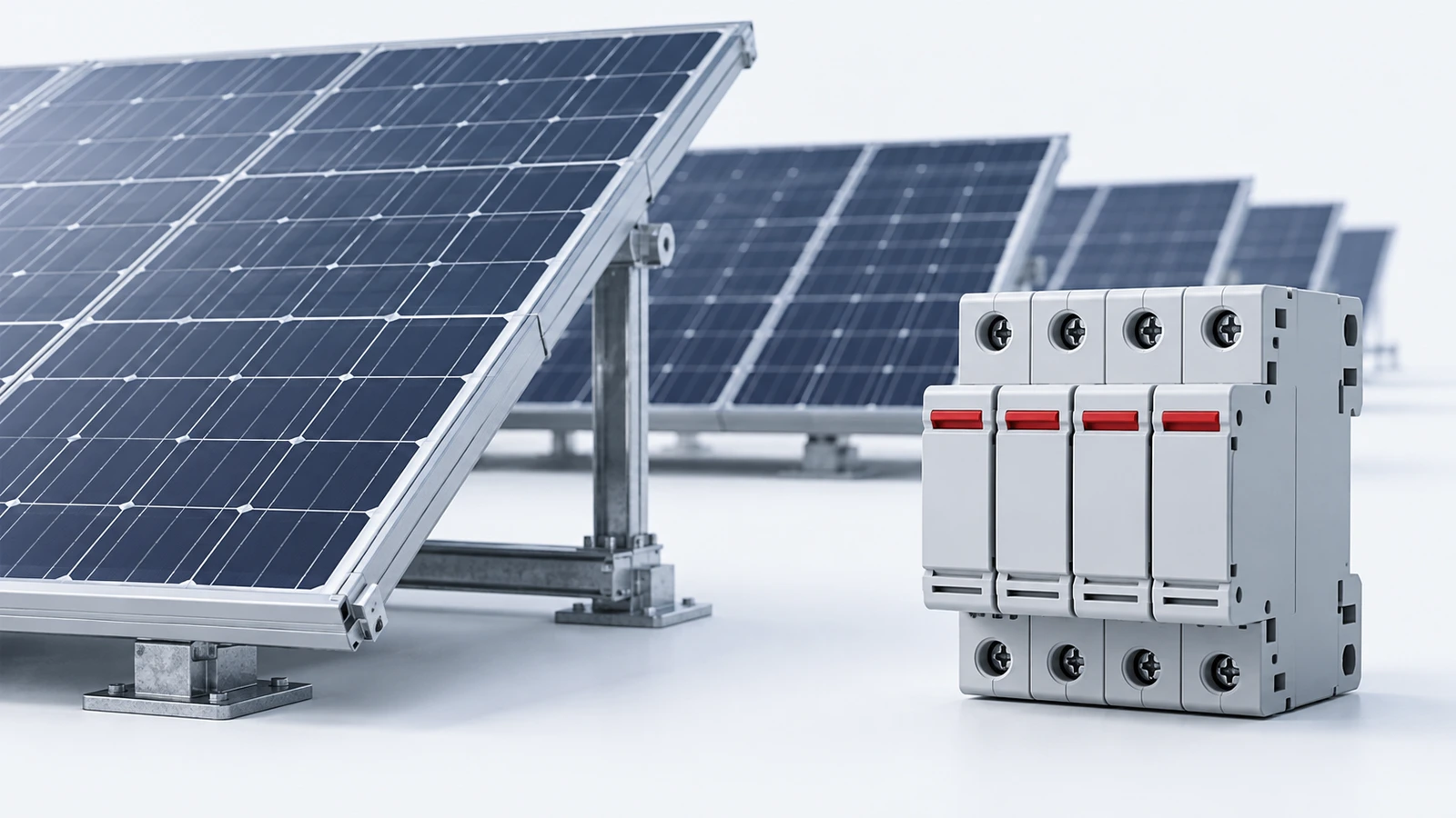
Use maximum voltage, not only operating voltage
An inverter’s normal operating point is not necessarily the highest voltage present on a PV string. Review the module’s open-circuit voltage, series count, temperature coefficient and the project’s design temperature basis. The result must be checked against all relevant equipment limits, including the inverter and disconnecting equipment.
For an arithmetic illustration, assume 12 modules in series, each with open-circuit voltage 49 V at a 25°C reference, a voltage coefficient of −0.28% per °C, and an assumed minimum module temperature of −10°C. The simple linear estimate is:
Vstring = 12 × 49 × [1 + 0.0028 × (25 − (−10))] ≈ 645.6 V.
Every input in that example is assumed. It is not a module specification or a complete code calculation. It shows why choosing a device from 12 × 49 = 588 V alone could overlook a higher voltage condition. Use the actual module data and the method required by the project.
Map the possible current paths
PV protection is not always adequately represented by the short-circuit current of one string. Parallel sources can feed a fault in another branch, and batteries introduce a different source of fault energy. Draw the actual source connections and identify which currents can reach the proposed device.
Collect module short-circuit current, string count, conductor data, module maximum series-fuse information and any other manufacturer limits. Apply the project’s required design factors and protective-device rules. Do not transfer a battery-breaker recommendation to a PV string because both circuits happen to be DC.
A PV switch-disconnector and a protective circuit breaker also have different duties. One may provide an isolation or switching function without providing the overcurrent protection needed elsewhere. Identify which functions the selected equipment is actually rated to perform.
Polarity and pole arrangements are product-specific
Some DC breakers are polarized. Others have different permitted arrangements, and some require specified poles in series for a stated voltage. The approved connection diagram is part of the application rating. It should be included in the design package and followed exactly.
Do not create a higher voltage rating by arbitrarily adding poles or copying a diagram from another product. Earthing arrangements and fault paths affect which poles must interrupt. Schneider Electric’s PV guide discusses how ground-fault conditions can change the voltage an interrupting path must withstand.
For this reason, a conceptual image of a PV protection system should not double as installation wiring. Terminal designations, polarity and connection details belong in the manufacturer-supported project drawing.
Check the enclosure and location
Outdoor solar equipment may operate in heat, direct sunlight, dust, moisture or corrosive conditions. The air inside an enclosure can differ substantially from the reported ambient weather temperature. Confirm equipment application limits and any required thermal assessment.
Also consider terminal compatibility, cable entry, maintenance access, labeling, UV exposure and the enclosure’s environmental protection. A suitable breaker inside an unsuitable enclosure does not make a suitable assembly. Conversely, an enclosure rating does not prove the internal device can carry the required current at the actual temperature.
A useful solar DC breaker enquiry
| Input | What to provide |
|---|---|
| Circuit location | String, combiner output, inverter input or battery branch |
| Voltage | Normal range and calculated maximum, with the temperature basis |
| Current | Operating and design current, source combinations and fault-current assessment |
| System arrangement | Earthing, polarity and required isolation functions |
| Device evidence | DC ratings, approved pole diagram, breaking capability and applicable standard |
| Installation | Enclosure, temperature, conductor and terminal information |
Require the supplier to identify the exact model and application conditions rather than reply only with a catalogue current rating. Any substitution should be reviewed against the same input schedule.
For the broader plant interface, the solar power substation guide covers a different system level. A suitable DC branch device does not establish the design of the AC collection or grid connection.
Common questions
Can I use an AC breaker on a solar DC circuit?
Only if the exact device has a suitable documented DC application rating and arrangement. Similar current ratings or physical dimensions do not establish suitability.
Does a high DC voltage rating cover every pole connection?
No. The rating may depend on a specified connection and system configuration. Read the application diagram and limitations.
Can the inverter being off make the PV circuit safe?
Do not assume so. PV modules can remain a source of voltage when illuminated. Isolation and safe working require the project’s approved procedure and competent personnel.