
 Huanghua Group Co., Ltd.
Solar Power Substation: How PV Plants Connect to the Grid
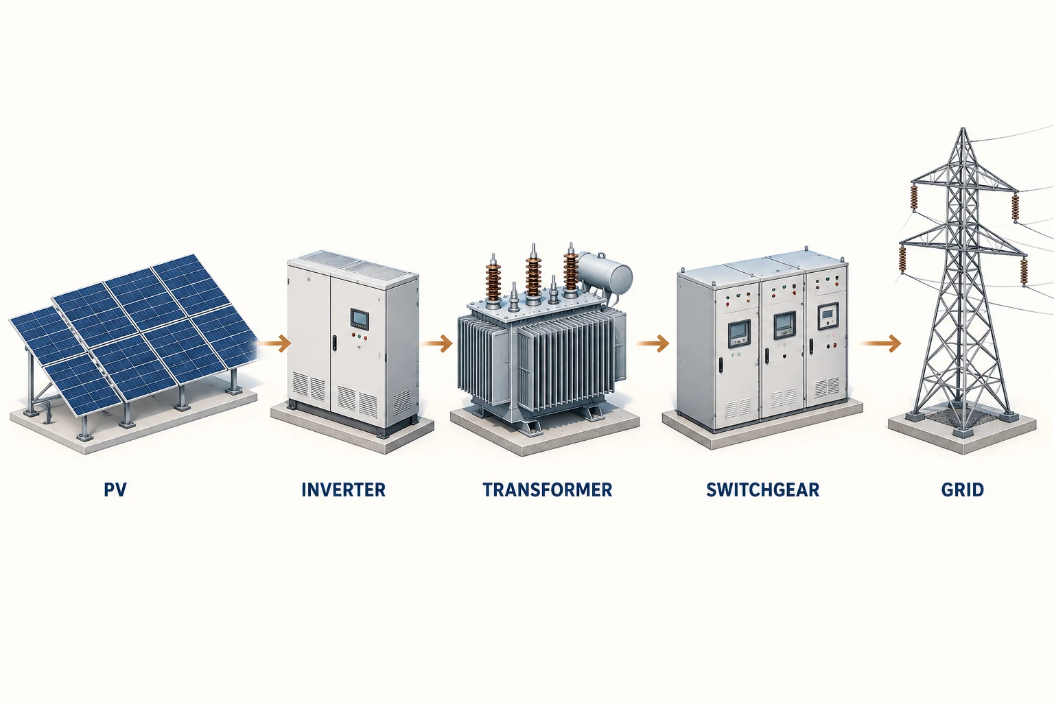
A solar power substation connects a photovoltaic plant’s electrical output to its collection network or grid interface. In a typical AC-coupled route, inverters convert PV-generated DC into AC, transformers provide the required voltage transformation, and switchgear provides the specified switching and protection interfaces.
The substation is therefore more than a transformer in an enclosure. Its design has to agree with the inverter system, the collection network and the grid connection requirements.
Follow the power path
PV modules produce DC electricity. Inverters convert it into AC suitable for their designed connection. The AC output may be collected and transformed to a higher distribution voltage, then routed through switching equipment toward the grid connection point.
Actual plants use different arrangements. An integrated inverter station, a distributed-inverter system and a larger collector substation will not necessarily place the same equipment in the same enclosure. The approved single-line diagram establishes the project’s boundaries.
Separate the equipment responsibilities
| Equipment or interface | Principal task | Information to align |
|---|---|---|
| Inverter | Converts DC to AC and performs its specified control functions. | AC output, operating limits and control requirements. |
| Transformer | Matches the required voltage levels. | Winding configuration, capacity, impedance and service duty. |
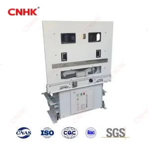
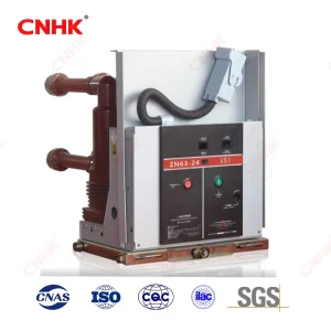
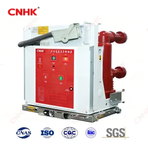
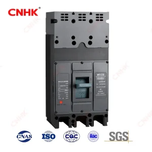
| Switchgear | Provides the specified switching and protective arrangement. | Ratings, circuits, interlocks and relay interfaces. |
| Metering and control | Supports the required measurement and plant operation. | Signals, communications and responsibility boundaries. |
| Grid connection | Defines the plant’s interface with the network. | Utility requirements and approved connection conditions. |
Distinguish an inverter station, collector substation and grid interface
| Level | Typical role | Scope question |
|---|---|---|
| Inverter / unit step-up station | Connects one inverter block or a defined group of inverters to the collection system through the specified transformation and switching. | Does the package include the inverter, transformer, switching, auxiliary supply and their internal connections? |
| Collector system or collector substation | Brings multiple generating blocks together and provides the required feeder switching/protection; a larger plant may have further transformation. | Which collection feeders, busbars, protection and controls are included? |
| Grid interconnection | Connects the plant at the agreed network boundary with the required protection, metering and operational interfaces. | Where is the point of connection, and which party owns each item? |
These are functional distinctions, not a rule that every solar plant must contain three separate buildings. A smaller installation can combine functions; a larger project may distribute them across several stations. Calling every enclosure a “solar substation” obscures those differences.
A scope example without assumed voltage levels
Imagine a project with four inverter blocks. Each block feeds a unit transformer, the four medium-voltage feeders reach a collector bus, and the agreed grid connection is beyond that bus through separately specified equipment. This is a hypothetical arrangement used to explain scope, not a Huanghua project reference.
A quotation for four prefabricated unit stations may cover the inverter-side interfaces, unit transformers and local switching. It does not automatically include the collector switchboard, a main step-up transformer if required, revenue metering, grid protection or the plant controller. The procurement schedule should identify each of those items as included, by others or not applicable.
Capacity needs the same discipline. If an illustrative AC operating point is 1 MW at a power-factor magnitude of 0.95, the corresponding apparent power is approximately 1 / 0.95 = 1.053 MVA. This calculation explains why DC array MW, AC real power and transformer MVA are not interchangeable. It does not select a transformer: thermal duty, inverter capability, harmonics, reactive-power requirements and applicable margins still require the project design.
Use one consistent interface table through enquiry, drawing review and acceptance. A changed inverter configuration or collector voltage must be reflected in the transformer and switchgear documents; otherwise individually plausible product offers can describe an incompatible plant.
The transformer must match the inverter interface
Check the inverter-side voltage, winding configuration and permitted system conditions using the selected inverter’s instructions. Manufacturer guidance also identifies frequency, system impedance and the generation/ambient profile as relevant transformer-selection inputs.
Do not apply one inverter family’s allowable connection arrangement to every PV system. A transformer proposal should name the intended inverter configuration or explicitly state the interface data used for design.
Capacity comparisons also need consistent units and duty assumptions. The PV array’s DC nameplate capacity is not, by itself, a complete transformer specification. Ask the designer to provide the intended AC operating duty and any relevant reactive-power or thermal requirements.
Grid requirements do not come from the enclosure
A prefabricated station can contain the selected equipment, but the enclosure does not establish compliance with a particular utility’s connection rules. Protection settings, metering, export control and required operational behavior must come from the approved project requirements.
Keep the connection point explicit. A supplier may be quoting a local inverter transformer station while the owner expects the complete grid substation. Both may use the phrase “solar substation,” yet the scope, equipment and price will be very different.
Use an interface schedule to prevent scope gaps
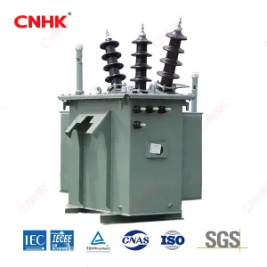
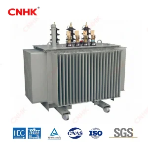
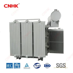
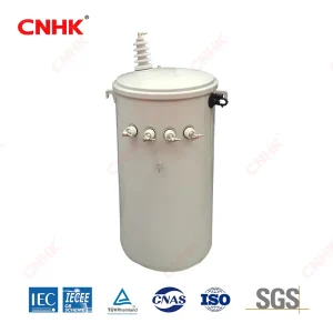
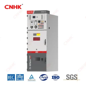
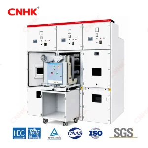
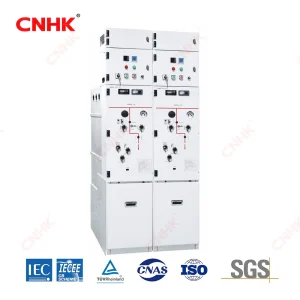
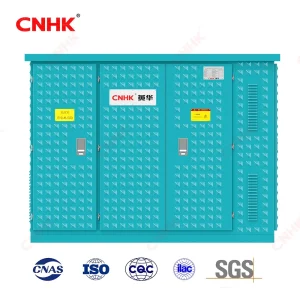
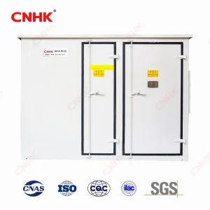
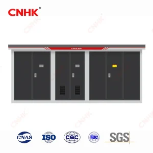
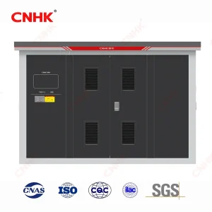
Huanghua’s prefabricated substation provides a relevant equipment route for an integrated station enquiry. The three-phase oil-immersed transformer is another product route when the transformer is supplied separately. Neither listing defines the complete EPC or grid-approval scope for a solar plant.
Documents to settle before equipment approval
Bring together the single-line diagram, inverter interface data, transformer schedule, switchgear circuit schedule and protection/control philosophy. Add the site conditions, equipment layout and delivery boundaries. Ask suppliers to mark deviations and unresolved assumptions against these documents.
The resulting package should show where power flows, which equipment performs each function and who is responsible for every interface. That gives the procurement and commissioning teams a common design basis without relying on a generic “solar-ready” label.