
 Huanghua Group Co., Ltd.
Transformer Wiring Diagram: How to Read Terminals, Windings and Connections
A transformer wiring diagram shows the electrical relationships needed to interpret the specified transformer’s connections. To use it correctly, match the diagram to the exact unit, read the winding and terminal labels, and follow its notes and revision information. A generic drawing cannot establish the correct connections for every transformer with a similar voltage rating.
Reading the diagram is also different from carrying out electrical work. The aim here is to understand the documents and identify missing information, not to provide a universal field-wiring procedure.
Start by identifying the kind of drawing
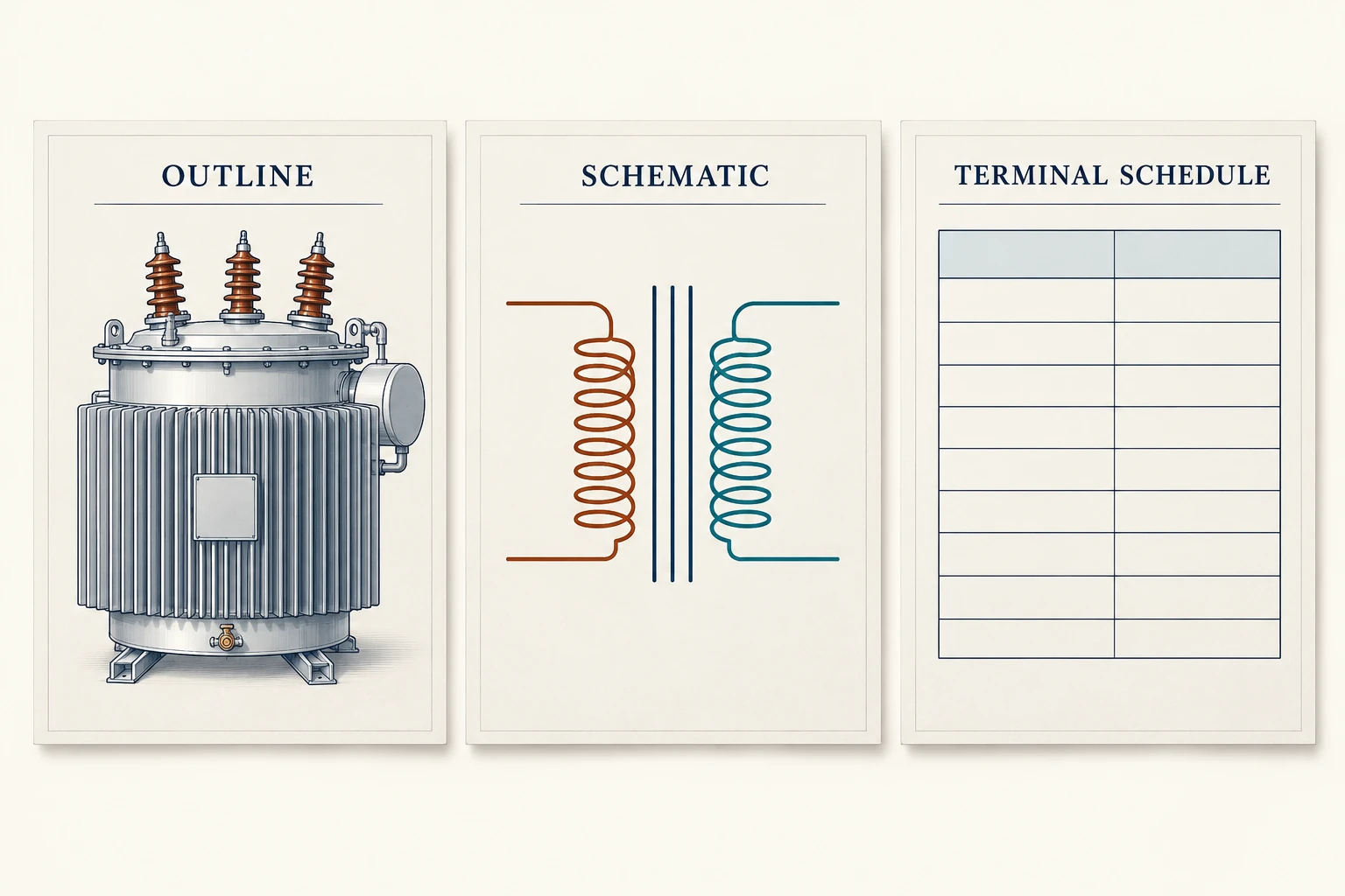
| Drawing | Main purpose | What it does not establish alone |
|---|---|---|
| Electrical schematic | Shows winding and circuit relationships. | The physical position of every connection. |
| Outline or general arrangement | Shows dimensions, mounting and equipment layout. | The complete electrical connection scheme. |
| Terminal schedule | Identifies terminals and their intended interfaces. | Every protection and operating requirement. |
| Single-line diagram | Shows the transformer’s role in the wider system. | All conductor-level details. |
These documents should agree. When an outline and a connection drawing identify different terminal arrangements, seek clarification before treating either as the approved installation basis.
A labelled two-winding schematic: read it in five steps
The diagram below is an original teaching schematic for an idealized two-winding transformer. H1/H2 and X1/X2 are illustrative terminal designations, not a connection drawing for a Huanghua unit. The windings are magnetically coupled but have no conductive connection to each other in this example.
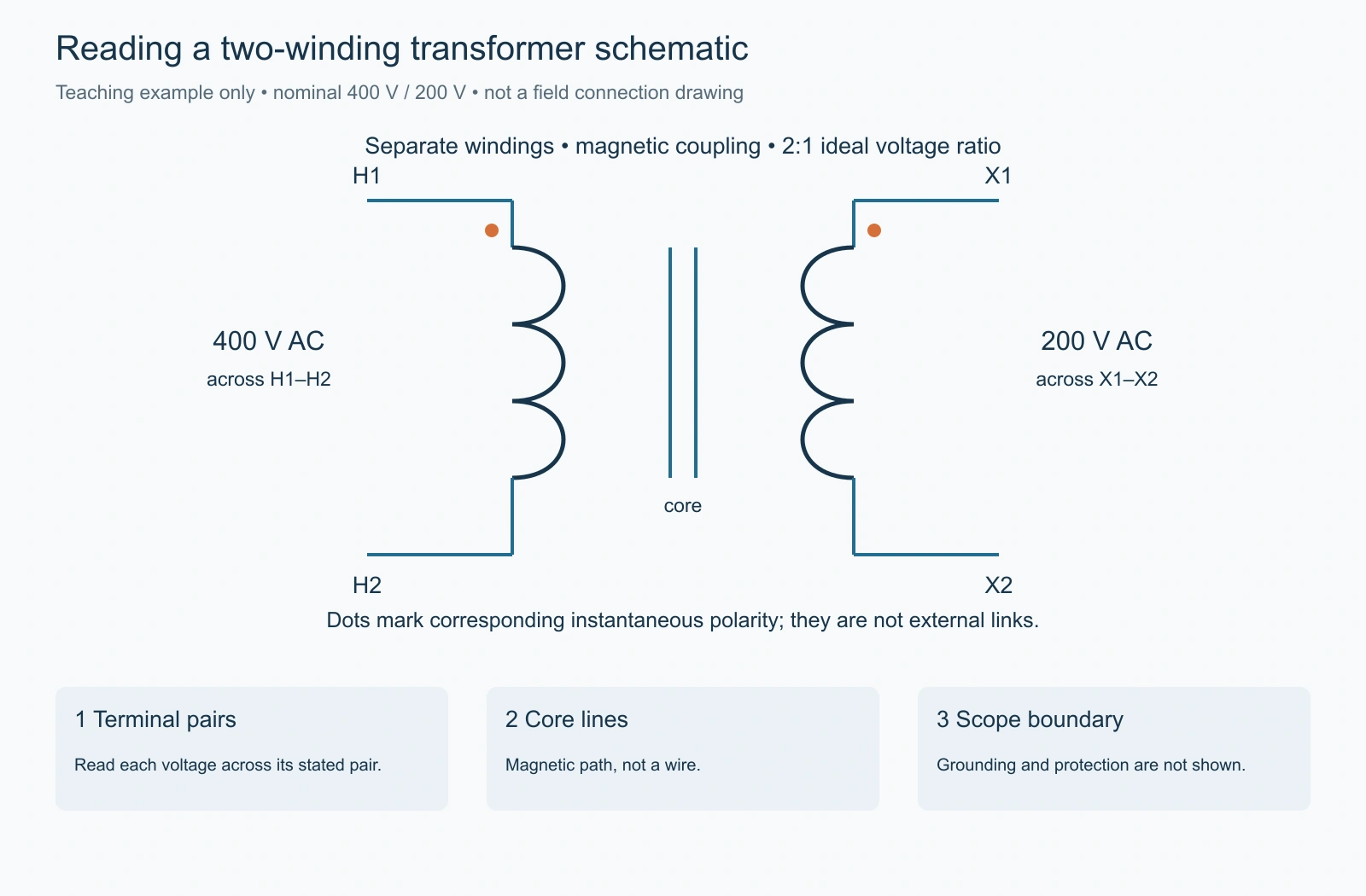
- Locate the two winding paths. H1 to H2 identifies one winding; X1 to X2 identifies the other. A line running through a coil symbol belongs to that winding path, not to the steel core.
- Identify the magnetic relationship. The parallel core lines indicate coupling through the magnetic core. They are not conductors to join to the winding terminals.
- Read the voltage labels across terminal pairs. In the example, 400 V refers to H1–H2 and 200 V to X1–X2. Neither label describes a voltage to an unspecified earth point.
- Read the polarity dots together. When H1 is instantaneously positive relative to H2, X1 is correspondingly positive relative to X2 under the marked reference. The dots express a relative polarity, not a command to bond the terminals together.
- Notice what is absent. No enclosure grounding, overcurrent protection, switching, cable sizes or installation connections are specified. Those omissions are intentional in a principle diagram and must be resolved in the actual project documents.
For the illustrated 2:1 ideal voltage ratio, a corresponding turns ratio is NH:NX = 2:1. That relationship explains the transformation. It does not tell the installer which supply conductors to land on an unfamiliar real unit, whether reverse operation is permitted, or what protective equipment is required.
Why a center tap changes the reading task
A center-tapped secondary has an accessible connection at the midpoint of its winding. In a hypothetical symmetric 240 V secondary, the full winding is 240 V end-to-end and each half is nominally 120 V relative to the midpoint. These labels describe different terminal pairs; they are not three interchangeable voltage measurements.
The actual terminal designation, midpoint availability, grounding arrangement and permitted load distribution come from the selected unit’s drawing. A schematic with only two secondary terminals does not establish that a center tap exists. Likewise, two drawn secondary winding sections do not by themselves authorize a particular series or parallel connection.
| Drawing feature | Meaning to establish | Common reading error |
|---|---|---|
| Terminal number or letter | A connection identifier defined by this drawing. | Treating a familiar label as universal across manufacturers. |
| Polarity dot | Relative instantaneous polarity of winding references. | Interpreting dots as compulsory external links. |
| Tap lead | Access to a specified winding point. | Assuming it is a separate fully rated output winding. |
| Junction mark | A conductive connection under the drawing’s convention. | Assuming every crossing line is connected. |
| Voltage table and revision | The permitted arrangements for the identified equipment version. | Combining a newer outline with an obsolete connection table. |
A practical reading exercise is to mark each voltage across its two stated terminals, highlight each winding path, and list the notes that govern the shown arrangement. If a required terminal pair or voltage option cannot be traced, record the missing information instead of inventing a connection from a generic internet diagram.
Read winding and terminal labels in context
Some manufacturer drawings use H designations on the high-voltage side and X designations on the low-voltage side. Other conventions also exist. The legend and the unit’s documentation control the interpretation; a familiar letter does not make an unfamiliar diagram interchangeable.
Primary and secondary describe the intended energy-transfer roles in an application, while high-voltage and low-voltage describe relative winding voltages. Do not assume that the physically upper terminals are always the supply connection or that the layout of a simplified schematic reproduces the equipment.
Polarity marks describe a relationship
Dots on winding symbols identify corresponding polarity. They matter when interpreting winding relationships and arrangements involving multiple windings or units. They are not a general instruction to connect all dotted terminals together.
For a document review, check that the polarity information belongs to the selected transformer and that any bank or parallel-operation design has been approved for the actual equipment. A copied diagram with the same number of coils is not sufficient evidence.
Taps are not the same as separate output windings
A tap provides access to a selected point on a winding and changes the effective turns used in the specified arrangement. Separate winding sections or secondary arrangements may serve different purposes. Read the manufacturer’s voltage table and connection notes together.
Do not infer permission to operate a tap mechanism under load. The equipment type and operating instructions determine how and when a change can be made. The approved setting should also be identifiable in the project records.
What to request with a distribution transformer
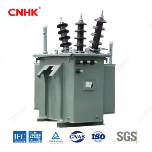
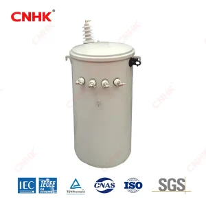
For the Huanghua single-phase distribution transformer, request the selected voltage/connection schedule, outline and terminal information as one coordinated package. The product family includes configuration options; the order-specific documents establish what is supplied.
Keep the final approved versions with the handover records. If the transformer is replaced or its application changes, confirm that the retained drawing still matches the asset rather than assuming the old connection information remains applicable.