
 Huanghua Group Co., Ltd.

















How Many Watts on a 20 Amp Circuit? Voltage and Load Assumptions
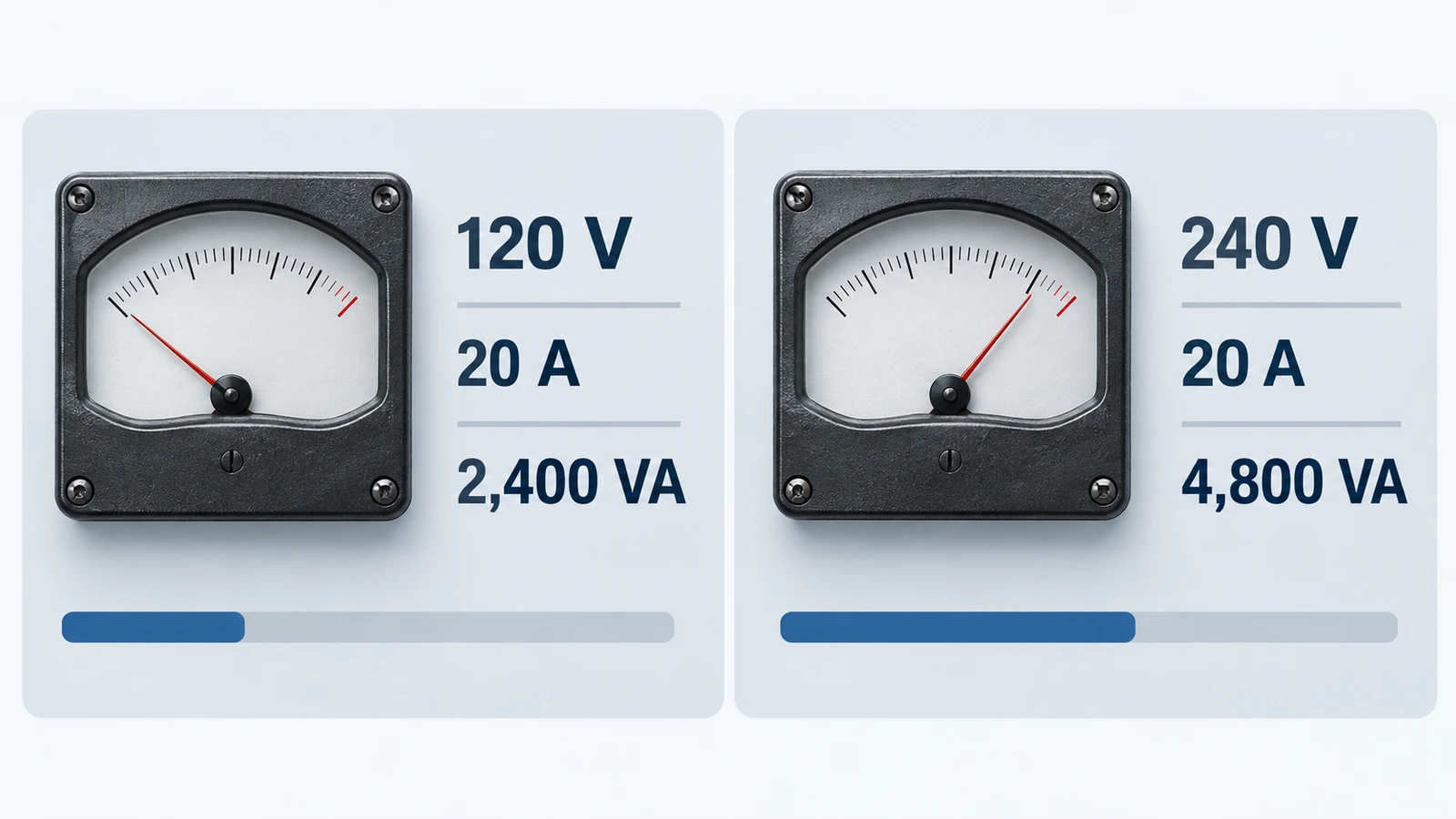
At 120 V, 20 A corresponds to 2,400 VA; at 240 V, it corresponds to 4,800 VA. Those values equal watts only at unity power factor. They describe electrical arithmetic, not a universal permitted load. The usable loading of a particular circuit also depends on duty, equipment ratings, conductors and the installation rules that apply.
That is why both “2,400 watts” and “1,920 watts” appear in answers about a 20 amp circuit. They can describe different assumptions. Before using either number, establish the voltage and whether the load is continuous under the relevant rules.
The voltage changes the answer
For a single-phase circuit, apparent power is voltage multiplied by current. Real power is voltage multiplied by current and power factor. At unity power factor, the two numerical values coincide, but the units still describe different quantities.
| Illustrative voltage | At 20 A | At 16 A | Meaning |
|---|---|---|---|
| 120 V | 2,400 VA | 1,920 VA | Watts equal these values only at PF = 1 |
| 230 V | 4,600 VA | 3,680 VA | Arithmetic example, not a national loading rule |
| 240 V | 4,800 VA | 3,840 VA | Check actual equipment voltage and circuit arrangement |
The 16 A column is simply 80% of 20 A. Including it does not mean every 20 A circuit worldwide must be limited to that value. The reason for applying a particular factor must come from the project’s code basis and equipment requirements.
Where the 80% figure comes from
In the US NEC context discussed by Schneider Electric, ordinary overcurrent sizing for a combination of continuous and noncontinuous loads uses the noncontinuous load plus 125% of the continuous load, with an exception for appropriately listed 100%-rated assemblies. The source describes a continuous load as one expected to remain at maximum current for three hours or more.
For a simple all-continuous example using the ordinary 125% relationship, a 20 A rating corresponds to 16 A of load: 20 / 1.25 = 16. At 120 V and unity power factor, that is 1,920 W. The same arithmetic at 240 V gives 3,840 W.
This is a scoped explanation of the familiar number. It does not override other requirements for specific appliances, circuits or installations. A 100%-rated application also depends on the complete listed arrangement and its conditions, not just an assertion that a breaker can carry its nameplate current.
Mixed continuous and noncontinuous loads
Consider an illustrative 120 V circuit with 10 A of continuous load and 6 A of noncontinuous load. Applying the ordinary sizing relationship gives 1.25 × 10 + 6 = 18.5 A. That arithmetic is different from simply allowing every combination up to 16 A.
If the noncontinuous portion rises to 8 A, the same calculation becomes 20.5 A. It no longer fits a 20 A rating under that assumed relationship. The correct response is to review the circuit design, not to assume that a short period below the breaker’s trip point makes the arrangement acceptable.
These examples explain a calculation method. A real circuit still needs all applicable checks, including conductor ampacity, terminal ratings, receptacle and equipment requirements, and any load-specific rules.
Power factor changes watts without changing amperes
At 120 V and 16 A, apparent power is 1,920 VA. If the load’s true power factor is 0.90, real input power is 120 × 16 × 0.90 = 1,728 W. The conductor still carries 16 A in this example even though the watt figure is lower.
This is why adding only the advertised output watts of computers, motors or electronic power supplies can misrepresent circuit loading. Check input ratings and operating data. Output power, maximum input current and measured consumption at a light load are different figures.
All outlets on the same circuit share its capacity
A room with several receptacles does not receive a separate 20 A allowance at each one. Loads connected to the same branch circuit contribute to the circuit’s total demand. Circuit identification matters when planning equipment placement.
Suppose two resistive devices are each rated 1,200 W at 120 V. Together they represent 20 A at the stated operating point, before other loads are considered. Whether that combination is permitted depends on duration, equipment instructions and the applicable rules. The arithmetic alone should not be presented as permission to run both indefinitely.
Starting current and cycling also matter. A motor may briefly draw more than its normal current. A thermostatic heater may cycle, but its design treatment cannot be guessed from a casual observation. Use the equipment’s rated information and the relevant calculation basis.
What to check before adding a load
- Confirm the actual voltage and which outlets or equipment share the circuit.
- Read electrical input ratings, not just advertised useful output.
- Identify continuous duty and any special rules for the equipment.
- Include existing loads and relevant starting behavior.
- Have conductor, connection and protective-device suitability assessed where the installation is being changed.
Repeated tripping, heat, discoloration or damaged accessories calls for investigation. A higher-rated breaker is not a capacity upgrade unless the rest of the circuit is designed and approved for the change.
Common questions
Does a two-pole 20 A breaker mean 40 A?
No. In a typical 240 V line-to-line example, 20 A flows through the load circuit and apparent power is 240 × 20 = 4,800 VA. Adding the pole ratings would double-count current.
Can I use 2,400 W continuously on a 120 V, 20 A circuit?
Do not assume so. The familiar ordinary US continuous-load example gives 1,920 W at unity power factor, and the actual circuit may have additional restrictions.
How do I calculate other voltages or three-phase loads?
Use the appropriate supply formula and state the power factor. The load factor guide also explains why average energy use does not establish peak circuit demand.