
 Huanghua Group Co., Ltd.









Shunt Trip Circuit Breaker: How It Works and What to Check Before Selection
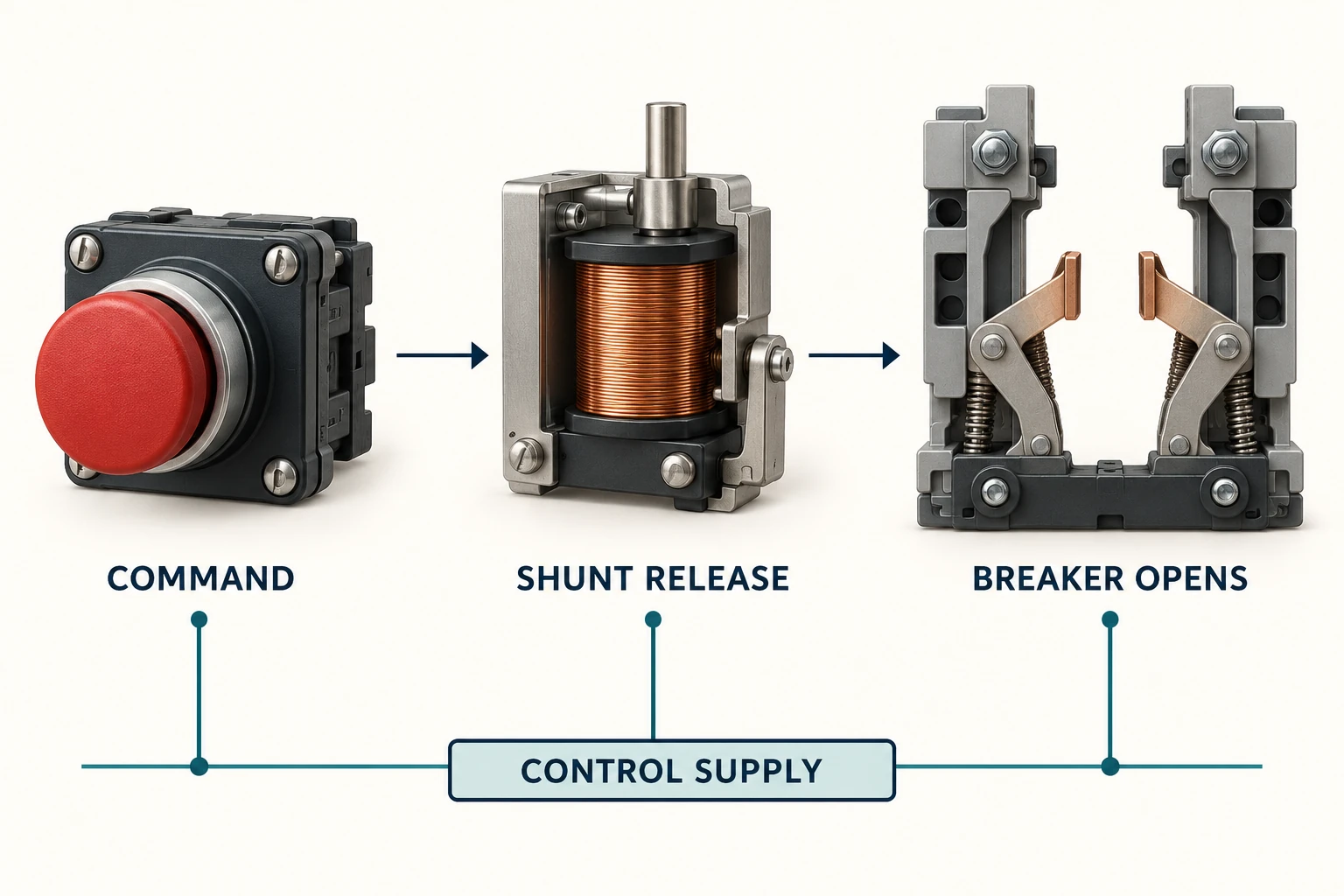
A shunt trip circuit breaker has an electrically operated release that can open the breaker when it receives the specified control signal. The command may come from a remote control or a protection/control system. The shunt release provides a way to command opening; it does not, by itself, detect every condition that should cause a trip.
Selection therefore has two parts: the breaker must suit the power circuit, and the release must suit the control circuit. Matching only the breaker’s main voltage is not enough.
How the opening command reaches the breaker
A compatible shunt release acts on the breaker’s opening mechanism when energized as specified by its manufacturer. The main contacts then open through the breaker mechanism. The accessory’s control supply is distinct from the main circuit it helps interrupt.
That distinction matters in an enquiry. A drawing may show a remote trip command, yet the accessory still requires the correct supply, signal duration and circuit arrangement. The phrase “remote trip” is a function request, not a complete accessory specification.
Shunt trip, undervoltage release and overcurrent protection
| Function | What initiates the action | What to avoid assuming |
|---|---|---|
| Shunt release | The specified electrical opening command. | That loss of the control supply will itself produce an opening command. |
| Undervoltage release | Supply voltage falling below the conditions specified for that release. | That it behaves like an energize-to-trip accessory. |
| Overcurrent protection | Current conditions evaluated by the protective device. | That adding a shunt release replaces the required protection function. |
Control philosophy determines which behavior the project needs. Where a system must respond to a failed supply or broken control path, that requirement belongs in the engineered control design. A shunt-release label alone does not establish a fail-safe system.
Confirm the accessory’s exact electrical duty
Request the control-voltage designation, AC or DC requirement, permitted operating range and energization duty from the selected accessory manual. Do not transfer a pulse-duration or continuous-duty claim from another manufacturer’s release.
Also identify what happens after an opening command. The project may require indication, a maintained lockout or a separate authorization to close. These are system behaviors to specify; they should not be inferred from the fact that the breaker has tripped.
A useful supplier response names the accessory part number and the breaker versions with which it is compatible. A generic “shunt trip included” line leaves too much room for an incompatible voltage or mechanical version.
Keep trip and closing functions distinct
An opening release and a closing command serve different purposes. Some product families use related accessory hardware in different mounting positions, but that is a model-specific design detail. It is not a reason to interchange accessories without the applicable instructions.
When reviewing a bill of materials, list opening, closing, undervoltage and indication functions separately. This makes omissions visible before the control schematic and equipment order are finalized.
Where the HKW1 option fits
The Huanghua HKW1 ACB description lists shunt release and undervoltage release options. That supports an enquiry for those functions, but the exact coil rating and energization conditions still require the selected accessory documentation.
Send the supplier the intended opening-command source, available control supply, required indication and the breaker configuration. Ask for the accessory schedule and control-interface drawing to be returned together. This keeps the command logic, supply and physical accessory tied to the same proposal.
Acceptance should verify the intended function
The project test plan should identify which command is being checked, which breaker should respond and which indication should change. The responsible testing team must use the equipment instructions and approved site procedure. Observing an open handle position alone does not verify the complete trip path or every interlock.