
 Huanghua Group Co., Ltd.













What Is a Core Balance Current Transformer? Earth-Fault Detection Explained
A core balance current transformer (CBCT) is a current sensor that detects residual current: the current that does not return through the conductors passing through its common sensing window. An earth fault can create that difference when current returns by a path outside the window.
The CBCT supplies a measurement to a compatible protection relay. It does not open the power circuit itself. Understanding that distinction helps engineers and buyers specify a complete earth-fault protection scheme, rather than purchase a sensor and assume the protection function is complete.
What is a core balance current transformer measuring?
A CBCT measures the combined current through its window, rather than the load current in one phase. In the ideal no-leakage condition, the currents cancel magnetically. Current leaving the monitored circuit through earth creates a residual signal because that return path is outside the measurement boundary.
For a three-phase, three-wire circuit, the phase conductors form the monitored group. In a four-wire circuit with a separate neutral and protective earth, the neutral belongs in that group too. The protective earth conductor stays outside the sensing window.
Unequal phase loads do not automatically mean an earth fault. Where neutral carries the load imbalance back through the same window, the complete current sum can still cancel. Looking only at whether the three phase currents are equal misses the purpose of the measurement.
This is a conceptual conductor arrangement, not an installation drawing. Cable screens, sheath bonding and the actual earthing system require the selected manufacturer’s application drawing. Their physical arrangement can affect what the sensor measures.
The sensor, relay and breaker do different jobs
The sensor detects; the relay evaluates; the switching device interrupts. In a typical separate-component protection scheme, the CBCT sends its signal to an earth-fault relay. The relay applies the configured operating criteria and produces an alarm or a trip command.
A circuit breaker must then carry out the interruption when tripping is required. Specifying a CBCT therefore leaves further decisions: which relay input accepts its signal, what action the relay should initiate, and how that action reaches the breaker.
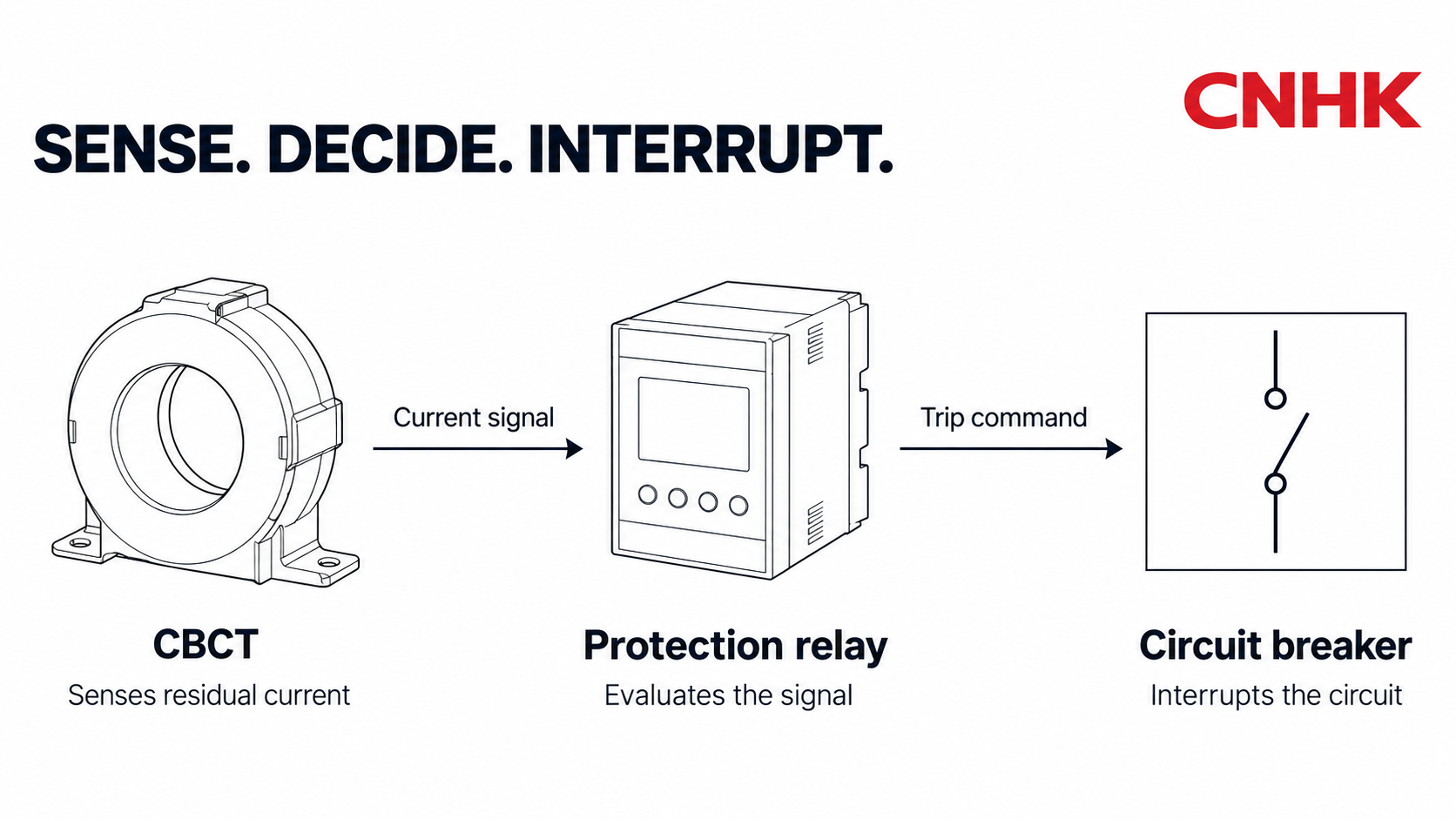
Keeping these roles separate also improves a supplier discussion. “CBCT included” identifies a component; it does not describe the complete alarm or trip function.
CBCT versus phase CT: measurement task comes first
A phase current transformer measures an individual phase. A core-balance arrangement measures the combined current in a common window. Protection relays can also obtain residual current from phase CT signals, so earth-fault detection is not exclusive to CBCTs.
| Arrangement | Measurement | Specification question |
|---|---|---|
| Individual phase CT | Current in one phase | Which metering or protection input needs this signal? |
| Core-balance CT | Residual current through a common window | Is this sensor matched to the required residual-current input? |
Split core describes construction, not the measurement task. A split-core CT opens mechanically around an existing conductor arrangement; a solid-core CT does not. Neither label alone establishes that a device is suitable for the intended residual-current protection scheme. Mechanical fit and electrical suitability need separate confirmation.
What determines useful detection sensitivity?
Useful sensitivity belongs to the complete sensor-and-relay arrangement. The name “CBCT” does not establish a universal minimum detectable fault current, operating time or personnel-protection rating.
CT saturation, conductor placement and the secondary lead circuit can affect the measurement. A protection design must account for the connected relay and its input requirements. Specifying only a large enough window leaves those electrical conditions unresolved.
Sensor technology also matters. Manufacturers specify particular measuring transformers for particular monitors and current types. A sensor suitable for one application should not be assumed to cover every AC or DC waveform.
For a buyer, the useful question is whether the offered combination meets the project requirement under its stated conditions. A generic sensitivity comparison between “CBCT” and “normal CT” cannot answer that. The project designer must select and coordinate the protection scheme; this overview does not provide operating settings.
How this fits a switchgear specification
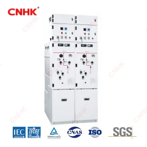
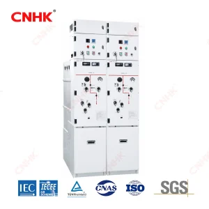
In medium-voltage switchgear, the physical sensing arrangement and the protection interface need to be considered together. Huanghua’s KYN28A-12(Z) air-insulated switchgear lists provision for a core-balance CT in the cable compartment and specified protection relays in the low-voltage compartment. Those provisions do not mean every supplied panel includes the same CT or relay.
A useful project handoff connects the compartment layout to the intended protection function. The supplier and protection designer should be able to answer these questions together:
- Measurement boundary: Which circuit and conductors are being monitored, and what drawing defines the cable and screen arrangement?
- Matched components: Which CBCT and relay input are offered as a compatible combination?
- Signal circuit: What lead length and secondary-circuit requirements are included in the design?
- Required response: Is the intended result an alarm, a trip command, or both, and which device completes that response?
The resulting offer should identify the sensor, relay and switching function as one coordinated scope. That is more informative than a bill of materials that simply lists “earth-fault CT.”