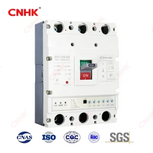
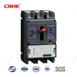
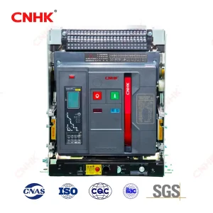
Overview
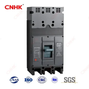
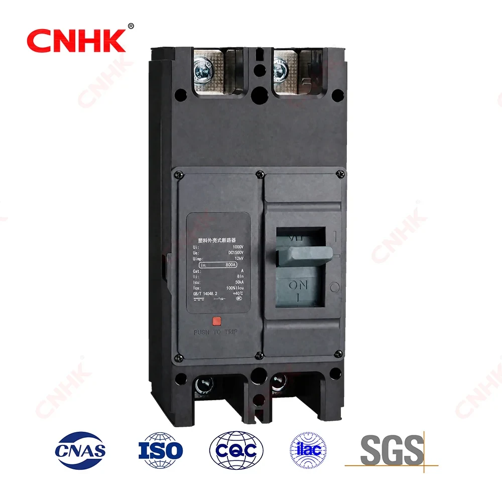
The DC / PV series is a DC circuit breaker for DC networks from DC250V to DC1500V, rated current 63–800A. With overload long-delay and short-circuit instantaneous protection, it distributes power and protects lines and power equipment against overload, short-circuit and other faults in photovoltaic arrays, battery energy storage systems (BESS), DC charging infrastructure and wind power DC collection circuits.
Why Choose Us
✓ Full DC range 250–1500V in ONE family (2P for 250–1500V, 3P for 1000–1500V)
✓ Icu up to 70kA at DC250/500V, Icu = Ics across the range
✓ DC arc extinction optimised — critical for safe DC interruption
✓ Series: □DC □PV — PV variant (DC250/500: 50kA) for solar combiner/inverter
✓ Isolation function (symbol —), Category A, GB/T 14048.1/.2 (IEC 60947-1/-2)
✓ 2P / 3P form factors; flexible front/rear/plug-in wiring
Key Features
| Sector |
Recommended |
| Full DC Voltage Range |
DC250–1500V in one frame family; 2P form for 250/500/750/1000/1500V, 3P form for 1000/1250/1500V. |
| High DC Breaking Capacity |
Icu up to 70kA at DC250/500V; Icu = Ics so rated capacity is retained after fault clearing. |
| Optimised DC Arc Extinction |
Contact & arc-chute geometry specifically designed for DC arc extinction — essential for safe interruption of DC currents. |
| DC & PV Variants |
DC variant for general DC distribution; PV variant (DC250/500V: Icu 50kA) tuned for solar combiner & inverter circuits. |
| Isolation + Safety |
Isolation function (symbol —), Category A; larger arcing distance (>50 / >100mm) than AC type reflects DC interruption demands. |
| Long Life & Wide Temp. |
Mechanical life 15,000–20,000 ops, electrical life 500–1500 ops; ambient -45°C to +70°C, altitude ≤2000m. |
| Flexible Wiring |
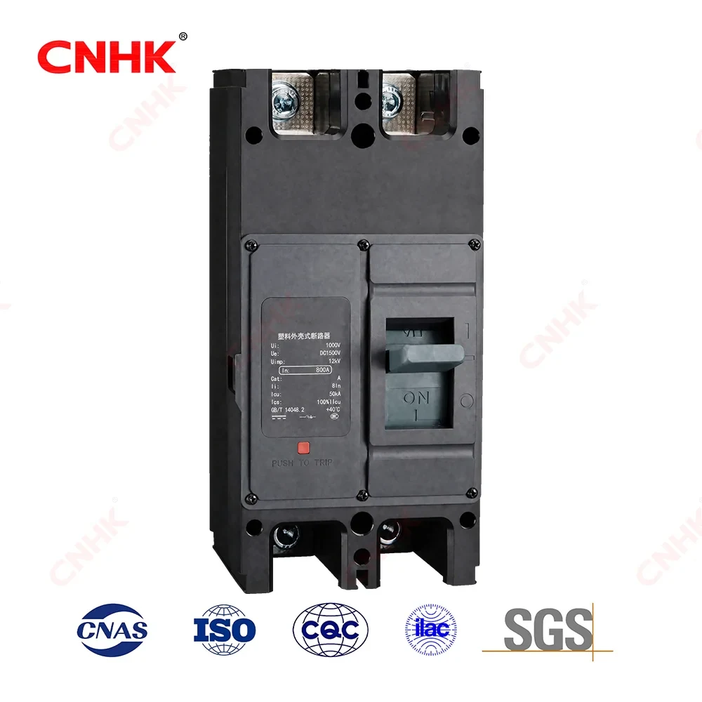
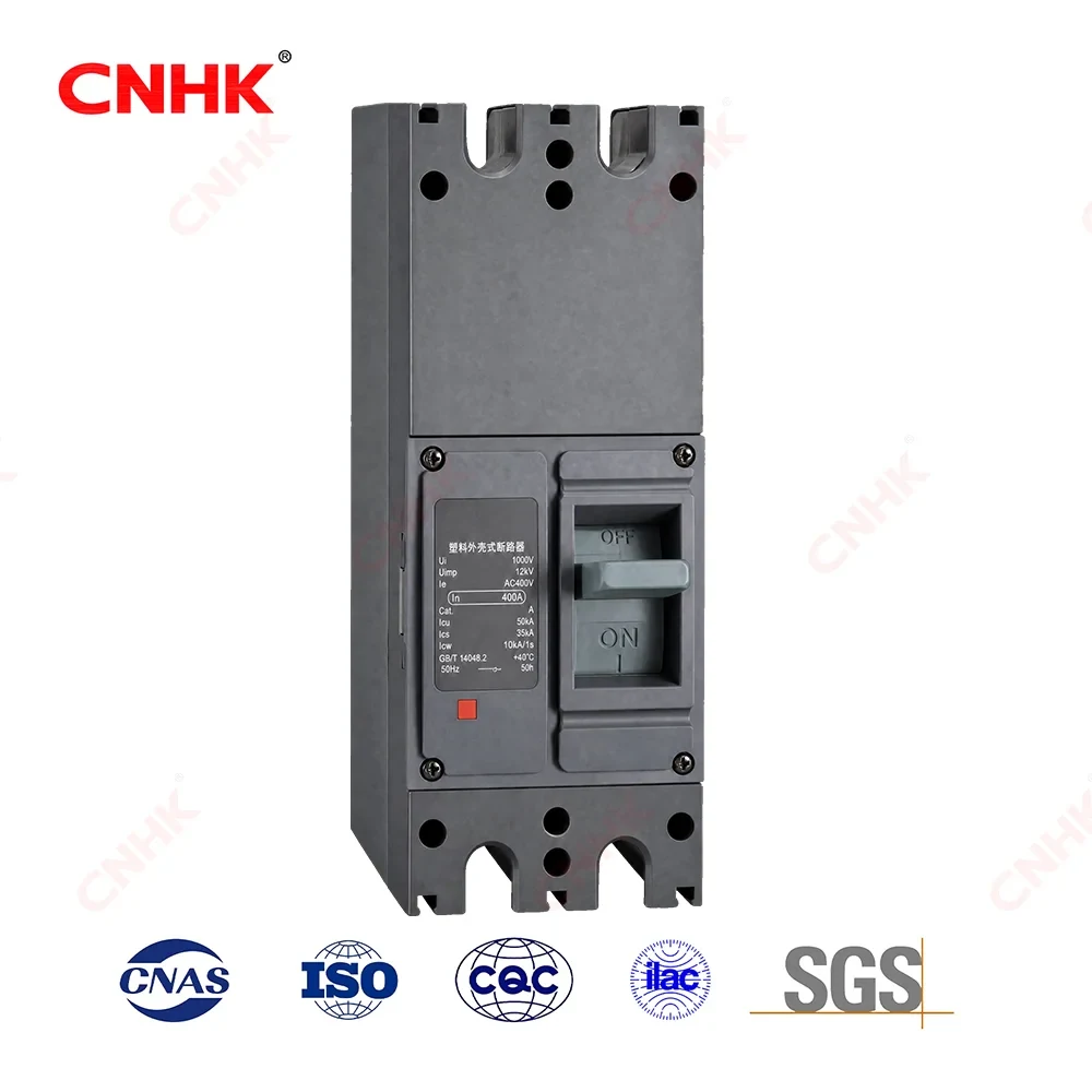
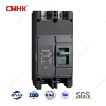
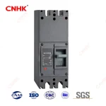
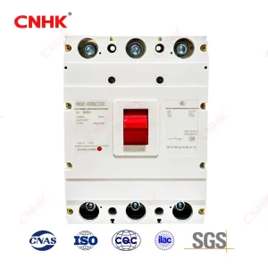
2P (Fig.1) & 3P (Fig.2/3) form factors; front / rear / plug-in wiring; 400V/630V frames available in 2P only. |
Applications
| Sector |
Recommended |
Value / Rationale |
| PV String / Combiner Box |
DC-250/315, 2P, DC1000/1500V |
DC1500V rating matches string & combiner box; 50kA Icu (DC250/500) for fault isolation. |
| PV Central Inverter |
DC-400/630 (PV), 2P/3P, DC1000/1500V |
PV variant protects DC link between combiner and central inverter; 3P form for 1000/1500V DC bus. |
| BESS — Battery Rack / PCS |
DC-630/800, 2P/3P, DC1000/1500V |
High breaking capacity handles battery fault currents; isolation for safe rack maintenance. |
| DC Fast Charging |
DC-250/400, 2P, DC1000V |
Protects DC bus inside EV fast charger; compact 2P form saves enclosure space. |
| Wind PV Hybrid |
DC-400/630, 2P/3P, DC1500V |
Covers 1500V DC collection bus for wind-solar hybrid microgrids. |
| DC Microgrid |
DC-250~800, 2P, DC750/1000V |
Modular protection across 250–1500V DC distribution; 2P for lower-voltage DC bus. |
| Off-grid Solar Home |
DC-250, 2P, DC250/500V |
Economical 50kA Icu at DC250/500V for small off-grid PV systems. |
Technical Parameters
| Scope & Standards |
| Item |
Parameter |
| Rated circuit |
DC networks DC250–1500V, rated current 63–800A |
| Protection |
Overload long-delay + short-circuit instantaneous protection |
| Series variant |
□ DC □ PV |
| Poles |
2P / 3P |
| Category |
A |
| Isolation |
Yes (symbol —) |
| Standards |
GB/T 14048.1; GB/T 14048.2 (equivalent to IEC 60947-1 / IEC 60947-2) |
| Main Technical Data (Frame 250–400) |
| Parameter |
Unit |
250 |
315 |
400 |
400V |
| Rated current In |
A |
63,80,100,125,140,160,180,200,225,250 |
280,300,315 |
250,315,350,400 |
250,315,350,400 |
| Rated insulation voltage Ui |
V |
1500 |
1500 |
1500 |
1500 |
| Rated impact resistance Uimp |
kV |
12 |
12 |
12 |
12 |
| Type |
— |
DC |
PV |
DC |
PV |
| Rated operating voltage Ue (2P) |
V |
DC250/500/750/1000/1500 |
DC250/500/750/1000/1500 |
DC250/500/750/1000/1500 |
DC250/500/750/1000/1500 |
| Rated operating voltage Ue (3P) |
V |
DC1000/1250/1500 |
DC1000/1250/1500 |
DC1000/1500 |
DC1000/1500 |
| Icu (2P) |
kA |
DC1000V:15 / DC1500V:5 |
DC250/500:50 / DC750/1000:25 / DC1500:7.5 |
DC250/500:25 / DC750/1000:15 / DC1500:10 |
DC250/500:50 / DC750/1000:25 / DC1500:10 |
| Icu (3P) |
kA |
DC1500V:20 |
DC1000/1250/1500:25 |
DC1000:30 / DC1500:25 |
DC1000:40 / DC1500:30 |
| Ics |
kA |
100% Icu |
100% Icu |
100% Icu |
100% Icu |
| Mechanical life |
operations |
20,000 |
20,000 |
20,000 |
15,000 |
| Electrical life |
operations |
1,500 |
1,500 |
1,000 |
1,000 |
| Flying arc distance |
mm |
≠50 |
≠50 |
>100 |
>100 |
| External dimensions (2P) |
mm |
200×78×135 |
200×78×135 |
270×130×158 |
275×106×178 |
| External dimensions (3P) |
mm |
200×107×138 |
200×107×138 |
270×182×158 |
— |
| Main Technical Data (Frame 630–800) |
| Parameter |
Unit |
630 |
630V |
800 |
800V |
| Rated current In |
A |
400,500,630 |
400,500,630 |
630,700,800 |
630,700,800 |
| Rated insulation voltage Ui |
V |
1500 |
1500 |
1500 |
1500 |
| Rated impact resistance Uimp |
kV |
12 |
12 |
12 |
12 |
| Type |
— |
DC |
PV |
DC |
PV |
| Rated operating voltage Ue (2P) |
V |
DC250/500/750/1000/1500 |
DC250/500/750/1000/1500 |
DC250/500/750/1000/1500 |
DC250/500/750/1000/1500 |
| Rated operating voltage Ue (3P) |
V |
DC1000/1250/1500 |
DC1000/1250/1500 |
DC1000/1500 |
DC1000/1500 |
| Icu (2P) |
kA |
DC250/500:25 / DC750/1000:15 / DC1500:10 |
DC250/500:50 / DC750/1000:25 / DC1500:10 |
DC250/500:25 / DC750/1000:15 / DC1500:10 |
DC250/500:50 / DC750/1000:25 / DC1500:10 |
| Icu (3P) |
kA |
DC1000:30 / DC1500:25 |
DC1000:40 / DC1500:30 |
DC1000:30 / DC1500:25 |
DC1000:40 / DC1500:30 |
| Ics |
kA |
100% Icu |
100% Icu |
100% Icu |
100% Icu |
| Mechanical life |
operations |
20,000 |
20,000 |
15,000 |
15,000 |
| Electrical life |
operations |
1,500 |
1,500 |
800 |
500 |
| Flying arc distance |
mm |
>100 |
>100 |
>100 |
>100 |
| External dimensions (2P) |
mm |
270×130×158 |
275×106×178 |
270×130×158 |
275×106×178 |
| External dimensions (3P) |
mm |
270×182×158 |
— |
270×182×158 |
— |
Note:Icu varies with Ue; 2P/3P dimensions differ; 400V & 630V frames are 2P only. For DC-400 and above 3P, terminals A&B are shorted at line side; for DC-250/315 3P, B&C are shorted.
| Power Loss (DC) (W) |
| Model |
Current |
Total power loss |
| DC-250 |
250A |
40 |
| DC-315 |
315A |
43 |
| DC-400 |
400A |
115 |
| DC-400V |
400A |
105 |
| DC-630 |
630A |
187 |
| DC-630V |
630A |
127 |
| DC-800 |
800A |
252 |
| Thermal Derating (DC) |
| Model |
40°C |
45°C |
50°C |
55°C |
60°C |
65°C |
70°C |
| DC-250 |
1.0In |
1.0In |
1.0In |
0.95In |
0.93In |
0.91In |
0.88In |
| DC-315 |
1.0In |
1.0In |
1.0In |
0.95In |
0.93In |
0.91In |
0.88In |
| DC-400 |
1.0In |
1.0In |
1.0In |
0.93In |
0.91In |
0.89In |
0.85In |
| DC-630 |
1.0In |
1.0In |
1.0In |
0.92In |
0.90In |
0.89In |
0.83In |
| DC-800 |
1.0In |
1.0In |
1.0In |
0.92In |
0.89In |
0.85In |
0.80In |
Note:No derating below +50°C. Reference ambient = +40°C.

 Huanghua Group Co., Ltd.