 Huanghua Group Co., Ltd.
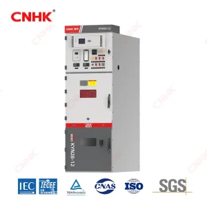
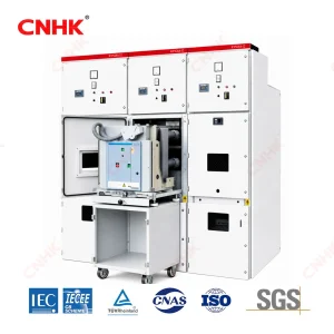
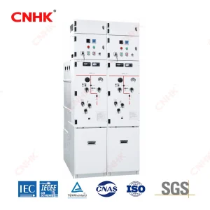
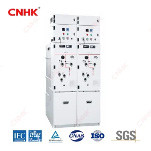
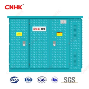
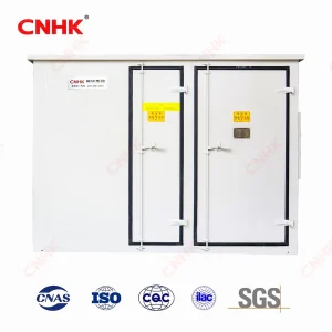
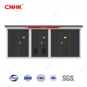
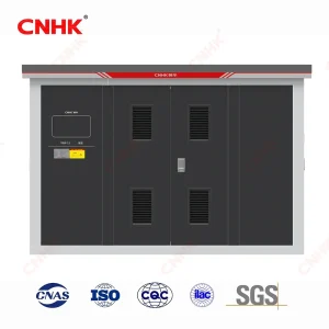
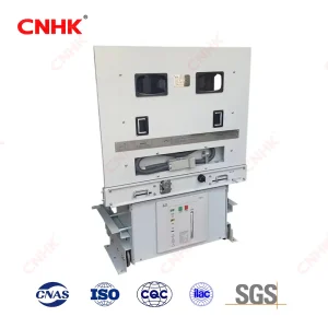
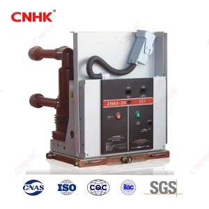
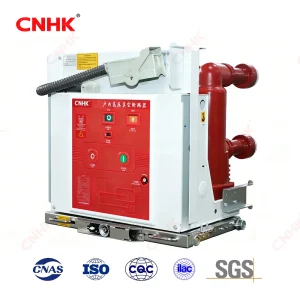
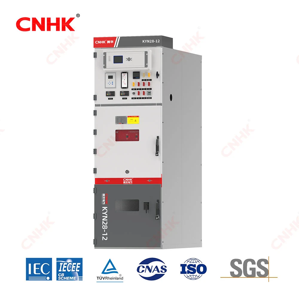
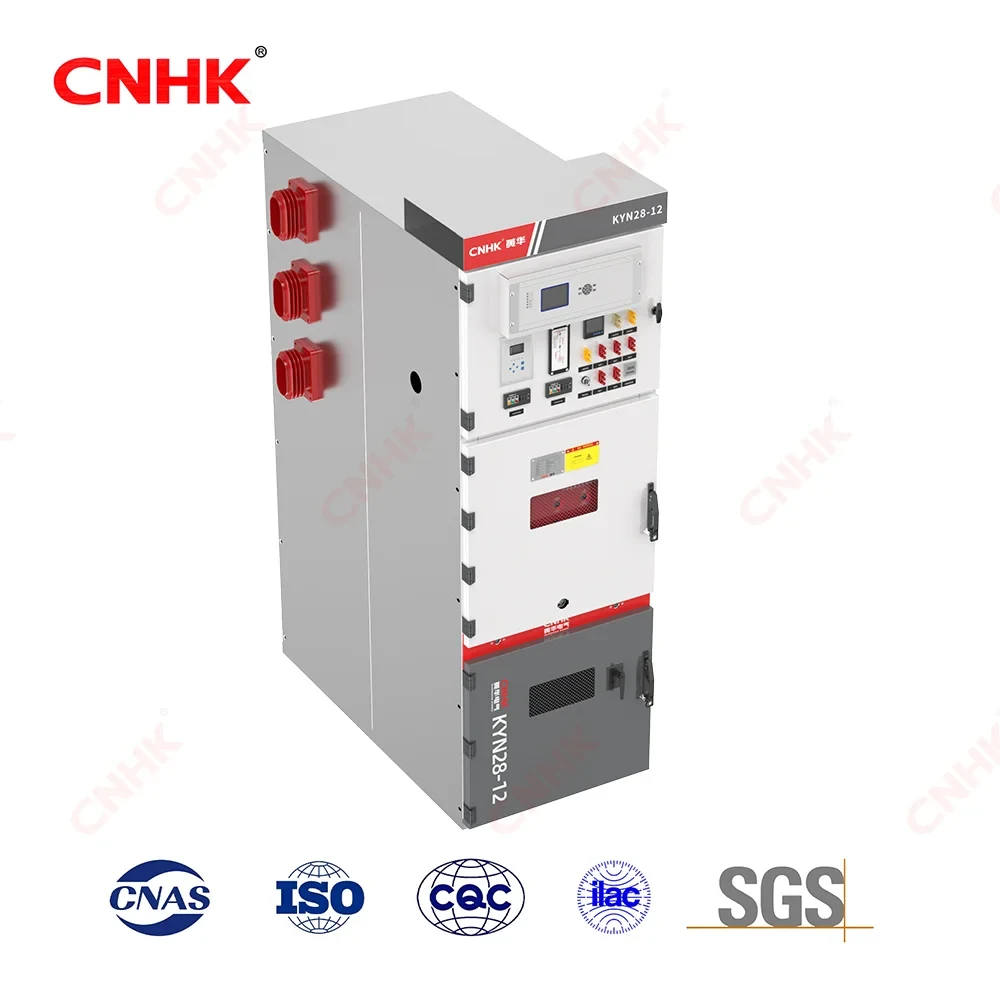
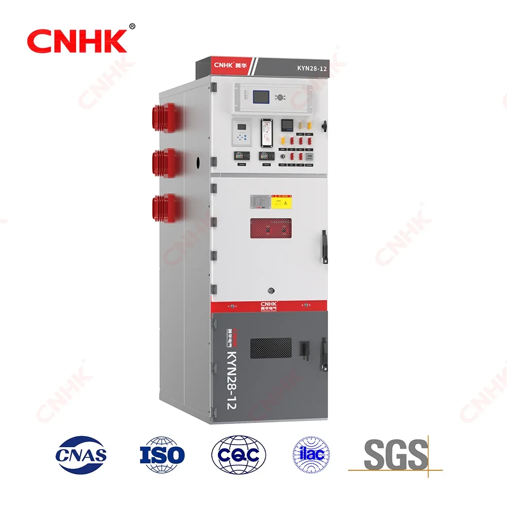
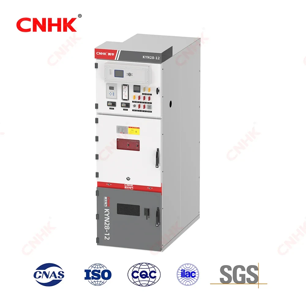
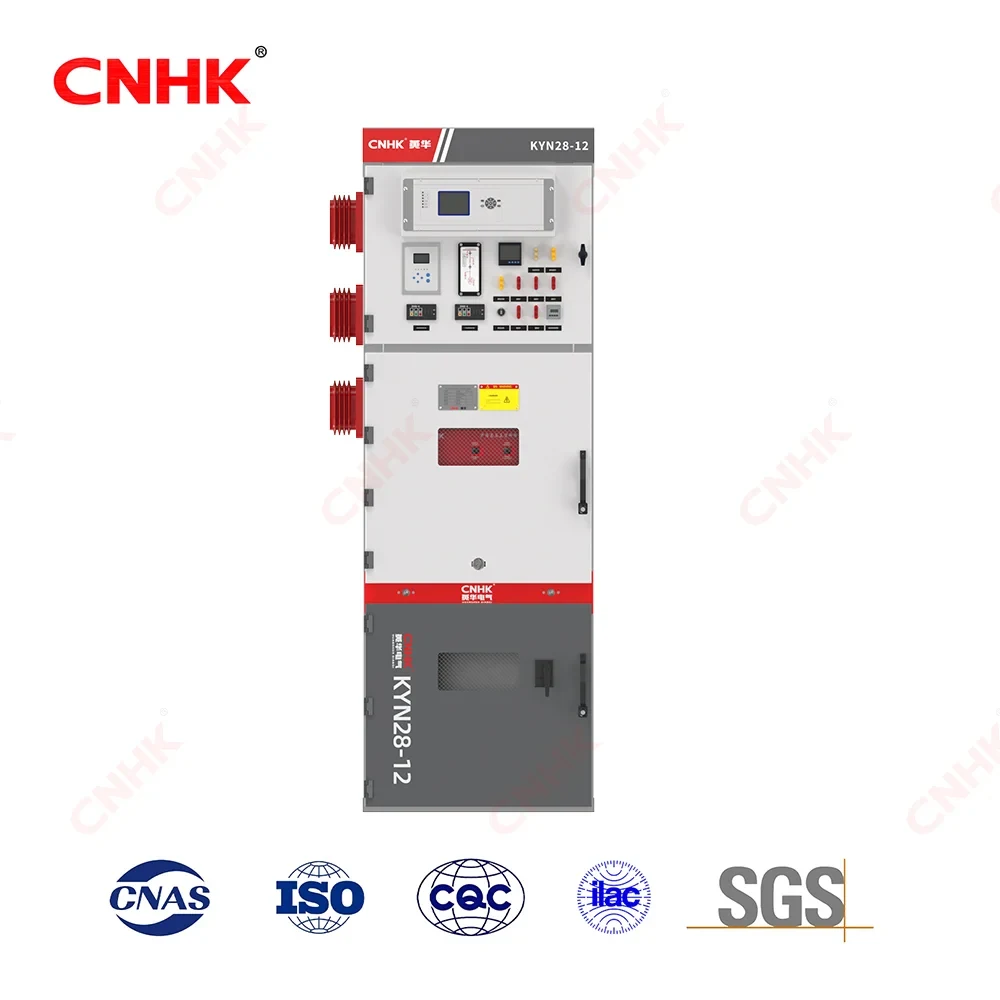
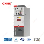
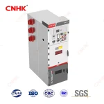
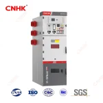
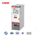
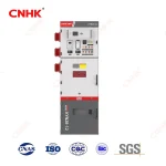
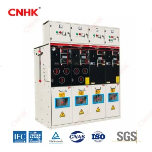
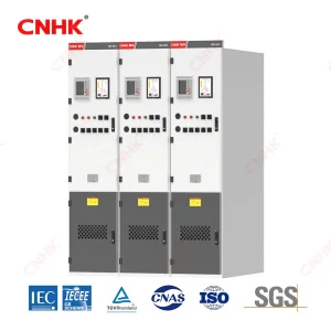
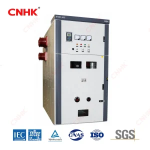
KYN28A-12(Z) · 12 kV Indoor Metal-Clad Withdrawable Air-Insulated Switchgear
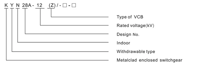
Type Designation
Working Condition
1 Ambient air temperature: -15°C ~ +40°C (-25°C ~ +45°C available as customized products).
2 Altitude: ≤1000m
3 Relative humidity: Daily average ≤95% Monthly average 90%
4 Earthquake intensity: ≤magnitude 8.
5 Water vapor pressure: Daily average <2.2kPa Monthly average ≤1.8kPa
6 Applicable in the places without steam, explosion, corrosive, and flammable gas
※Note: Customized products are available.
Key Highlights
-
Withdrawable vacuum breaker compartment — the breaker is mounted on a withdrawable part, allowing isolation, testing and replacement from the front. Benefit: reduces the outage scope during maintenance.
-
Compartmented metal-clad construction — busbar, breaker, cable and low-voltage compartments are separated by metal partitions with pressure-relief paths. Benefit: limits the propagation path of an internal fault when designed, tested and maintained accordingly.
-
Front access and closed-door racking — main operations and routine maintenance are performed from the front; the withdrawable part can be racked in/out with the compartment door closed. Benefit: supports safer routine operation in confined substations.
-
Five interlocking functions: prevention of load-breaking by the disconnector, incorrect breaker operation, energising with the earthing switch closed, earthing a live circuit and access to live compartments; plus the IEC 62271-200 mandatory interlocks between withdrawable part, breaker, earthing switch and door.
-
Wide rating coverage — 630–5,000 A, 16–50 kA breaking, 16–50 kA / 4 s short-time withstand, 40–125 kA peak withstand, with 650 / 800 / 1,000 mm panel widths. Benefit: one platform covers final distribution through main incomer duties.
-
Flexible breaker and protection options — VS1 (ZN63A) or VD4 vacuum circuit breaker; the low-voltage compartment accepts specified numerical relays, meters and communication interfaces. Benefit: easier integration into existing protection and SCADA systems (subject to interface conditions).
Applications
-
10/12 kV distribution rooms in factories, industrial parks, commercial complexes and high-rise buildings — incomer, bus-tie, feeder, PT and capacitor panels.
-
Urban 10 kV switching stations, distribution rooms and the HV side of prefabricated substations, configurable for 25 kA / 31.5 kA fault levels.
-
MV collection and export circuits of PV, wind and BESS plants — subject to defined system voltage, short-circuit contribution, protection scheme, earthing and grid code.
-
Primary and secondary distribution for rail transit, data centres, hospitals, airports, water and municipal works.
-
Export packages for ASEAN, Middle East, Africa and LATAM with English documentation, layout drawings and type-test material (scope confirmed per project).
Product Features
| Title (EN) | Description (EN) |
| Metal-Clad Withdrawable Construction | Metal-clad, indoor, withdrawable (centrally mounted) design: the enclosure is assembled from folded aluzinc / high-grade steel plate for strength and corrosion resistance; the circuit breaker is mounted on a withdrawable part that can be fully removed for service or replacement. |
| Four Metal-Segregated Compartments | Four independent compartments — busbar (A), circuit-breaker (B), cable (C) and relay/meter (D) — separated by metal partitions with pressure-relief channels, so internal fault energy is directed outwards and does not endanger adjacent panels or personnel. |
| Five Interlocking Functions | Complete five interlocking functions: prevention of load-breaking by the disconnector, incorrect breaker operation, energising with the earthing switch closed, earthing a live circuit and access to live compartments; IEC 62271-200 mandatory interlocks are also satisfied. |
| Three-Position Withdrawable Part | Driven by a racking mechanism, the withdrawable part moves between connected, test and disconnected positions with mechanical indication and latching; withdrawal under load is prevented, and secondary circuits can be commissioned in the test position. |
| VS1 / VD4 Vacuum Circuit Breaker | Standard VS1 (ZN63A) indoor HV vacuum circuit breaker; VD4 (ABB type) or an equivalent is available on request. Spring-stored operating mechanism with electrical close/open plus manual emergency operation. |
| Busbar & Contact System | Main and branch busbars use tin-plated electrolytic copper with bus bushings, contact boxes and fixed contact assemblies; main-to-branch joints are bolted with washers, giving low contact resistance and ample temperature-rise margin. |
| Earthing Switch & Earth System | The cable compartment houses a JN15 earthing switch; a continuous main earthing busbar runs through the panel, the frame protective conductor is bonded to the substation earth grid, and shield earthing positions are provided. |
| Cable Compartment & Terminations | The generous cable compartment supports bottom cable entry/exit and overhead incoming/outgoing schemes, accommodating CTs, the earthing switch, surge arresters and a core-balance CT, with provisions for cable clamping and sealing. |
| Shutters & Personnel Safety | Shutters close automatically when the withdrawable part is removed, screening the live fixed contacts; forced mechanical interlocks between the door, earthing switch and breaker prevent access to live compartments. |
| Low-Voltage Compartment & Secondary Interface | The relay/instrument compartment is fully segregated from HV parts and houses protection relays, meters, the control mini-busbar, terminal blocks and an anti-condensation heater; an aviation plug enables quick make/break of secondary circuits. |
| Front Access & Wall-Standing | Installation, commissioning and maintenance are all performed from the front; the panel can stand against a wall or be arranged back-to-back, saving floor space with greater layout flexibility and operational safety. |
| Environmental Adaptability | For indoor service: ambient −15 °C to +40 °C (customised −25 °C to +45 °C available), altitude ≤ 1,000 m, daily average humidity ≤ 95 % and monthly ≤ 90 %, seismic intensity up to magnitude 8; for locations free from steam, explosive, corrosive and flammable gases. |
Technical Parameters
1. Ratings & Insulation
| Parameter | Unit | Data / Value | Standard |
| Rated voltage (highest voltage for equipment) | kV | 3.6 / 7.2 / 12 | IEC 62271-200 |
| System voltage | kV | 12 | IEC 62271-200 |
| Rated frequency | Hz | 50 (AC 50/60 Hz available) | IEC 62271-1 |
| Rated current of circuit breaker | A | 630 / 1250 / 1600 / 2000 / 2500 / 3150 / 4000 / 5000 | IEC 62271-100 |
| Rated current of switchgear | A | 630 / 1250 / 1600 / 2000 / 2500 / 3150 / 4000 / 5000 | IEC 62271-200 |
| Rated short-circuit breaking current | kA | 16 / 20 / 25 / 31.5 / 40 / 50 | IEC 62271-100 |
| Rated short-time withstand current | kA | 16 / 20 / 25 / 31.5 / 40 / 50 | IEC 62271-200 |
| Rated short-circuit duration | s | 4 | IEC 62271-200 |
| Rated peak withstand current | kA | 40 / 50 / 63 / 80 / 100 / 125 | IEC 62271-200 |
| Rated short-circuit making current (peak) | kA | 40 / 50 / 63 / 80 / 100 / 125 | IEC 62271-100 |
| 1 min power-frequency withstand voltage — between poles, pole to earth | kV | 24 / 32 / 42 | IEC 62271-200 |
| 1 min power-frequency withstand voltage — across open contacts | kV | 24 / 32 / 48 | IEC 62271-200 |
| Lightning impulse withstand voltage (peak) — between poles, pole to earth | kV | 40 / 60 / 75 | IEC 62271-200 |
| Lightning impulse withstand voltage (peak) — across open contacts | kV | 46 / 70 / 85 | IEC 62271-200 |
| Rated power-frequency withstand voltage (auxiliary / as stated) | kV | 42 / 1 min | IEC 62271-200 |
| Degree of protection — switchgear shell | — | IP3X | IEC 60529 |
| Degree of protection — compartments (doors opened) | — | IP2X when the CPT and CB doors are open | IEC 60529 |
2. IEC 62271-200 Classification
| Parameter | Unit | Data / Value | Standard |
| Product standard | — | IEC 62271-200 (AC metal-enclosed switchgear and controlgear) | IEC 62271-200 |
| Domestic equivalent standard | — | GB 3906 | GB 3906 |
| Type of enclosure | — | Metal-clad (armoured), withdrawable | IEC 62271-200 |
| Insulation medium | — | Air-insulated (AIS) | IEC 62271-200 |
| Loss of Service Continuity (LSC) | — | — | IEC 62271-200 |
| Partition class (PM / PI) | — | — | IEC 62271-200 |
| Internal Arc Classification (IAC) | — | On request | IEC 62271-200 Annex AA |
| Withdrawable part | — | Circuit-breaker truck (withdrawable part) | IEC 62271-200 |
| Interlocking | — | Five interlocking functions + IEC mandatory interlocks | IEC 62271-200 / GB 3906 |
| Rated filling pressure / gas | — | Not applicable (air-insulated) | — |
3.Mechanical / Layout Data
| Parameter | Unit | Data / Value | Standard |
| Structure | — | Panel body + centrally mounted withdrawable part | IEC 62271-200 |
| Compartments | — | A busbar / B circuit-breaker / C cable / D relay & meter | IEC 62271-200 |
| Panel width (A) | mm | 650 / 800 / 1000 | Manufacturer catalogue |
| Panel height (B) | mm | 2300 | Manufacturer catalogue |
| Panel depth (C) — cable outgoing feeder | mm | 1500 | Manufacturer catalogue |
| Panel depth (C) — overhead incoming & outgoing | mm | 1660 | Manufacturer catalogue |
| Width 650 mm condition | — | Branch bus ≤ 1250 A and heat-stable current ≤ 31.5 kA | Manufacturer catalogue |
| Width 800 mm condition | — | Branch bus ≤ 1250 A and heat-stable current ≤ 40 kA | Manufacturer catalogue |
| Width 1000 mm condition | — | Branch bus ≥ 1600 A | Manufacturer catalogue |
| VS1 type — max rated current / altitude | — | Rated current ≤ 3150 A, altitude ≤ 1000 m | Manufacturer catalogue |
| VD4 type — max rated current / altitude | — | Rated current ≤ 5000 A, altitude ≤ 1000 m | Manufacturer catalogue |
| 4,000–5,000 A arrangement | mm | 1000 × 1500 (1660) × 2300 (flat-top) | Manufacturer catalogue |
| Bus connection | — | Main bus + branch bus + bolt + pad | Manufacturer catalogue |
| Mounting | — | Indoor, floor-mounted, front access | Manufacturer catalogue |
| Arrangement | — | Against the wall or back-to-back double row | Manufacturer catalogue |
4.Main Components
| Parameter | Unit | Data / Value | Standard |
| Vacuum circuit breaker | set | ZN63A (VS1) or VD4 × 1 | IEC 62271-100 |
| Current transformer | pcs | LZZBJ9 series × 3 | IEC 61869-2 |
| Earthing switch | set | JN15 × 1 | IEC 62271-102 |
| Surge arrester | pcs | HY5W × 3 (per scheme) | IEC 60099-4 |
| Voltage transformer | pcs | JDZ10-10 × 2 / JDZX10-10 × 3 (per scheme) | IEC 61869-3 |
| HV fuse (PT protection) | pcs | RN2-10 × 3 (per scheme) | IEC 60282-1 |
| Protection relay / metering / SCADA | — | As specified in the enquiry | IEC 60255 / IEC 62053 |
5.Service Conditions
| Parameter | Unit | Data / Value | Standard |
| Ambient air temperature | ℃ | -15 to +40 (-25 to +45 as customised) | IEC 62271-1 |
| Altitude | m | ≤ 1000 | IEC 62271-1 |
| Relative humidity | % | Daily average ≤ 95; monthly average ≤ 90 | IEC 62271-1 |
| Water vapour pressure | kPa | Daily average ≤ 2.2; monthly average ≤ 1.8 | IEC 62271-1 |
| Earthquake intensity | magnitude | ≤ 8 | IEC 62271-2 / GB 50260 |
| Site conditions | — | No steam, explosion, corrosive or flammable gas | IEC 62271-200 |
6. Standards, Tests & Documents
| Parameter | Unit | Data / Value | Standard |
| Design reference | — | IEC 62271-200 and GB 3906 | IEC / GB |
| Related standards | — | IEC 62271-100 (VCB), IEC 62271-102 (earthing switch), IEC 60529 (IP) | IEC |
| Type tests | — | Dielectric, temperature rise, short-circuit making/breaking, short-time withstand, mechanical endurance, IP verification | IEC 62271-200 |
| Routine tests | — | Power-frequency withstand, main & earthing circuit resistance, VCB timing, interlock function, wiring & visual inspection | IEC 62271-200 |
| Type-test documentation | — | Available for the stated ratings and arrangements | CNAS |
| Documents with offer | — | GA drawing, single-line diagram, technical data sheet, BOM, routine test plan, packing list | Project |