 Huanghua Group Co., Ltd.
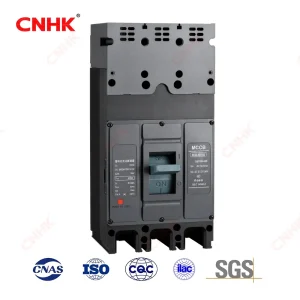
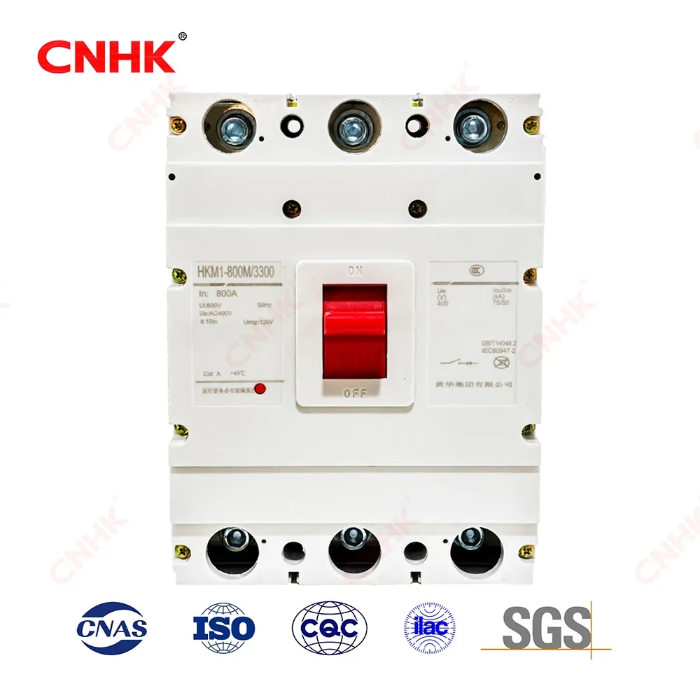
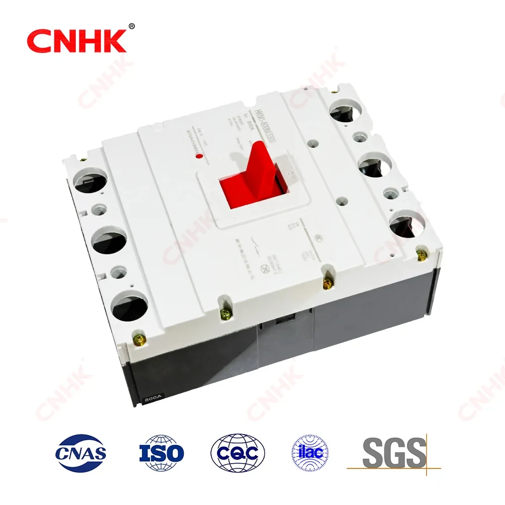
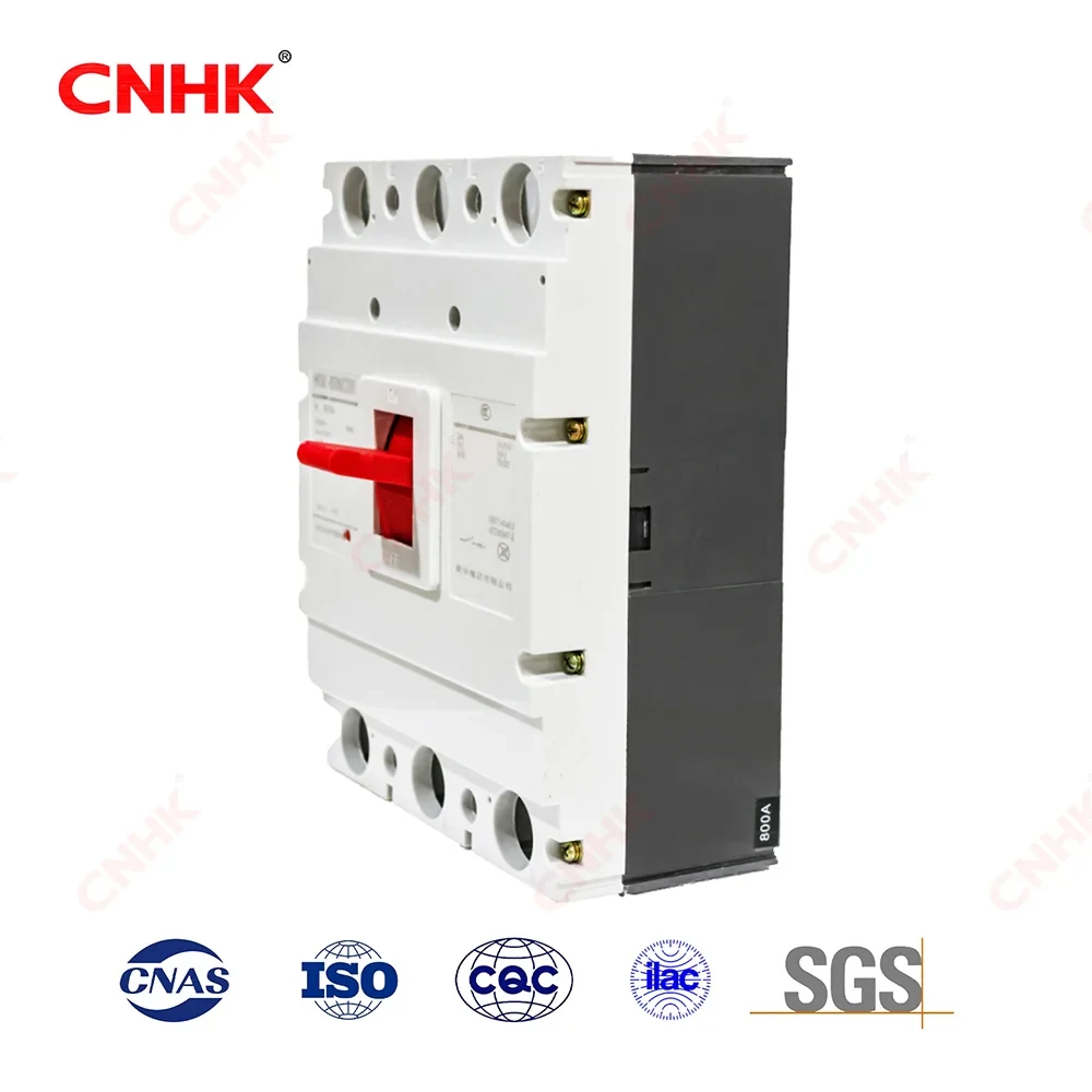
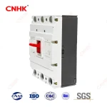
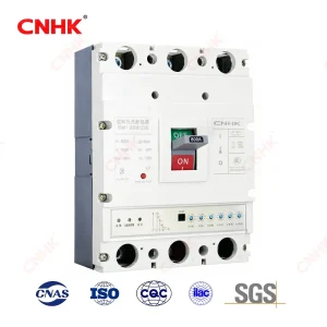
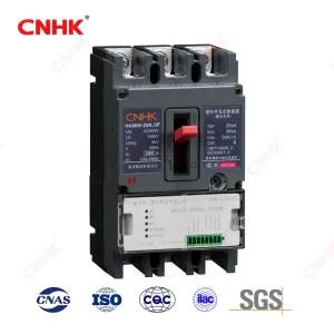
HKM1 Series Molded Case Circuit Breaker (MCCB)
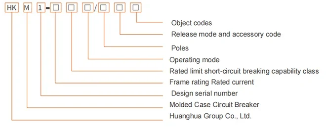
Model and its meaning
Applicable workingenvironment and installation conditions
Elevation of installation site 2000m and below;
Ambient medumtemperature is not higher than +4o° C and notlower than-5°C; and the average value of 24 hours does not exceed 35°C (except for special orders);
The relative humidity of the air at the instalation site shall not exceed 50% at the highest temperature of +40° C; there may be higherrelative humidiy at lower temperatures, the monthly average minimum temperature of the wettest month shall not exceed +25C, andthe monthy average maximum relative humidity of the month shallnot exceed 0%, and the condensation on the surface of the productdue to temperature change shall be considered;
The pollution level shall be Grade 3;
Protection class: IP20;
The installation category of the main circuit of the crcuit breaker is l and the auiliary crcuit and control circuit not connected to the main circuit are installed in category Il;
In the medium without explosion hazard. and the medium has no gas and conductive dust sufficientto corrode metal and destroyinsulation;
In the place without rain and snow attack;
Circuit breaker should be installed according to the product manual.
Note:
-
Circuit breaker for power distribution has no code; circuit breaker for protection motor is represented by “2”
-
No code for direct operation of handle; P for electric operation; Z for rotating handle.
-
According to the number of product poles, itis divided into two poles (100, 225 type), three poles and four poles (HKM1-1250, 1600 without four poles). There are four types of neutral pole (N pole) in quadrupole products Type A: N pole is notequipped with overcurrent tripping elements, and N pole is always on, not closed with other three poles,
-
Type B: N pole is not equipped with overcurrent tripping element, and N pole is closed together wth other three poles;(N poleis closed first and then divided) Type C: N pole is equipped with overcurent tripping element, and N pole is cosed togetherwth other three poles (N pole is closed first and then divided) Type D: N pole is equipped with overcurrent tripping element.and N pole is always connected, not closed together with other three poles.
-
According to rated current: HKM1 -63 is 6, 10, 16, 20, 25, 32, 40, 50, 63A nine levels (6A specification without overloadprotection); HKM1-125 is 10, 16, 20. 25. 32, 40, 50, 63, 80. 100, 125Aeleven levels; HKM1 -250 is 100. 125, 140. 160. 180.200, 225, 250A eight levels: HKM1-400 is 250. 315, 350, 400A: HKM1-630 is 400. 500, 630A. HKM1-800 is 630. 700 and
800A. -
According to the connection mode, it can be divided into three types: front connection, rear connection and plug-in connection.
-
According to the type of overcurent release, it can be divided into two types: thermal-electromagnetic (compound) type and electromagnetic (instantaneous) type
-
According to the accessory device, itis divided into two types: with accessory device and without accessory device.
-
Accessory devices are divided into internal devices and external devices
-
Internal devices include shunt trip, undervoltage trip, auxiliary contact and alarm contact;
-
Exteral devices include rotary handle operating mechanism, motor operating mechanism, interlocking mechanism and connecting terminals of auxiliary devices, etc.
Product Introduction
| Product Positioning | The HKM1 series Molded Case Circuit Breaker (MCCB) is suitable for AC 50/60Hz circuits with rated working voltage up to 690V and rated current up to 1600A. It distributes power and protects lines and supply equipment against overload, short-circuit and undervoltage. | The full range covers eight frame grades: 63/125/250/400/630/800/1250/1600A. |
| Highlights | ① Rated insulation voltage Ui=800V, max. working voltage 690V;
② Ultimate short-circuit breaking capacity Icu up to 75/100kA (large frames); ③ Compact size, high breaking capacity, short/zero arcing distance; ④ Thermal-magnetic / magnetic trip and rich accessories available. |
It serves both power distribution and motor protection purposes. |
| Advantages | Advanced structure, stable performance and long service life;
inverse-time overload + instantaneous short-circuit protection; front / rear / plug-in connection; expandable with motor operation, shunt/undervoltage release, auxiliary/alarm contacts for automated distribution. |
Installation Category III (Main Circuit), Pollution Level 3 |
| Standards | Complies with IEC 60947-1, IEC 60947-2 and GB/T 14048.1, GB/T 14048.2 low-voltage switchgear standards (subject to nameplate and latest catalogue). | Independent websites are advised to include both IEC and GB specifications to benefit domestic and international SEO. |
| Applications | Industrial plant distribution, motor circuit protection, data center & commercial building low-voltage distribution, new-energy and infrastructure power distribution systems. | It can be used in conjunction with HKW series frame circuit breakers to build a complete power distribution solution. |
Product Features
Compact, light-weight and easy to install in compact switchgear and distribution boxes.
High breaking capacity with short/zero arcing distance for enhanced switchgear safety.
Inverse-time thermal trip + instantaneous electromagnetic trip for overload & short-circuit protection.
Thermal-magnetic and magnetic trip types for distribution / motor protection applications.
Front, rear and plug-in connection to suit various switchgear structures.
Rich accessories: shunt release, undervoltage release, auxiliary/alarm contacts, motor/rotary handle mechanism.
Four N-pole configurations (A/B/C/D) for 4-pole products in 3Ph+N systems.
Wide operating range: altitude ≤2000m, -5℃~+40℃, pollution degree 3.
IP20, main circuit installation category III, control circuit cat. II, excellent electrical & mechanical endurance.
Compliant with IEC 60947-1/2 and GB/T 14048 series — widely accepted for global markets.
Technical Parameters
| Parameter | Value | Description |
| Frame / rated current In | 63 / 125 / 250 / 400 / 630 / 800 / 1250 / 1600 A | The housing is divided into eight grades, each containing multiple rated current levels. |
| Poles | 2P / 3P / 4P | HKM1-1250/1600 does not have a four-pole design; the four-pole N-pole has four types: A/B/C/D. |
| Rated insulation voltage Ui | 800 V | Main circuit electrical clearance and creepage distance reference |
| Rated working voltage Ue | 690 V and below up to 690 V | Suitable for 690V/400V/230V systems |
| Arcing distance | 0 / ≤50 / ≤100 mm (depending on model) | HKM1-63M has a zero arc flash (0mm), and the large frame is ≤100mm. |
| Ultimate short-circuit breaking capacity Icu | 30/50/65/75 kA (depending on model) | HKM1-63M=30kA; HKM1-800=75kA |
| Rated service short-circuit breaking capacity Ics | 25/35/50 kA (depending on model) | Ics is the 25/35/50kA corresponding value of Icu. |
| Overload protection (thermal) | Inverse-time | Thermal trip reverse time limit: 1.05In no action, 1.30In action. |
| Short-circuit protection (magnetic) | Instantaneous | Power distribution 10In±20%; Motor 12In±20% |
| Trip unit type | Thermo-electromagnetic (compound) / Electromagnetic (instantaneous) | 200 = Electromagnetic only; 300 = Thermo-electromagnetic; 000 = No tripping |
| Installation category | Main loop III / Control loop II | Main circuit III / control circuit II |
| Pollution degree | Grade 3 | |
| Protection class | IP20 | |
| Ambient temperature | -5℃ ~ +40℃ (24h average ≤35℃) | Special orders can be expanded |
| Installation altitude | ≤ 2000 m | |
| Connection type | Front/Rear/Plug-in | Three connection methods are available |
| Operation | Handle / Electric (P) / Rotary handle (Z) | Direct handle has no code; P = electric; Z = rotary handle |
| Application | Power distribution (no code) / Motor protection (2) | Motor protection type model includes ‘2’ |
| Compliance standards | IEC 60947-1 / IEC 60947-2; GB/T 14048.1/.2 | Based on the factory nameplate and the latest sample |
| Mechanical endurance | 10,000 cycles (partial shell) | HKM1-63/125/250
/400 is for 10,000 times. |
| Electrical endurance | 2000~10000 cycles (depending on model/current) | See main technical specifications table |
Main technical performance indicators
| Model | Rated Current | Poles | Rated insulation voltage | Rated working voltage | arcing distance (mm) | ICU | ICS | Operability(times) | |
| energized | not energized | ||||||||
| HKM1‑63M | 6、10、16、20、25、32、40、50、63 | 2,3,4p | 800V | 690V and below | 0 | 25 | 2000 | 10000 | |
| 30 | |||||||||
| HKM1‑125M | 10、16、20、25、32、40、50、63、80、100、125 | 0( ≤ 50) | 30 | 25 | 2000 | 10000 | |||
| 35 | |||||||||
| HKM1‑250M | 100、125、140、160、180、200、225、250 | ≤ 50 | 50 | 35 | 2000 | 10000 | |||
| HKM1‑400 | 250、315、350、400 | ≤ 100 | 65 | 50 | 2000 | 10000 | |||
| HKM1‑630 | 400、500、630 | ≤ 100 | 60 | 50 | 1000 | 5000 | |||
| HKM1‑800 | 630、700、800 | ≤ 100 | 75 | 50 | 1000 | 5000 | |||
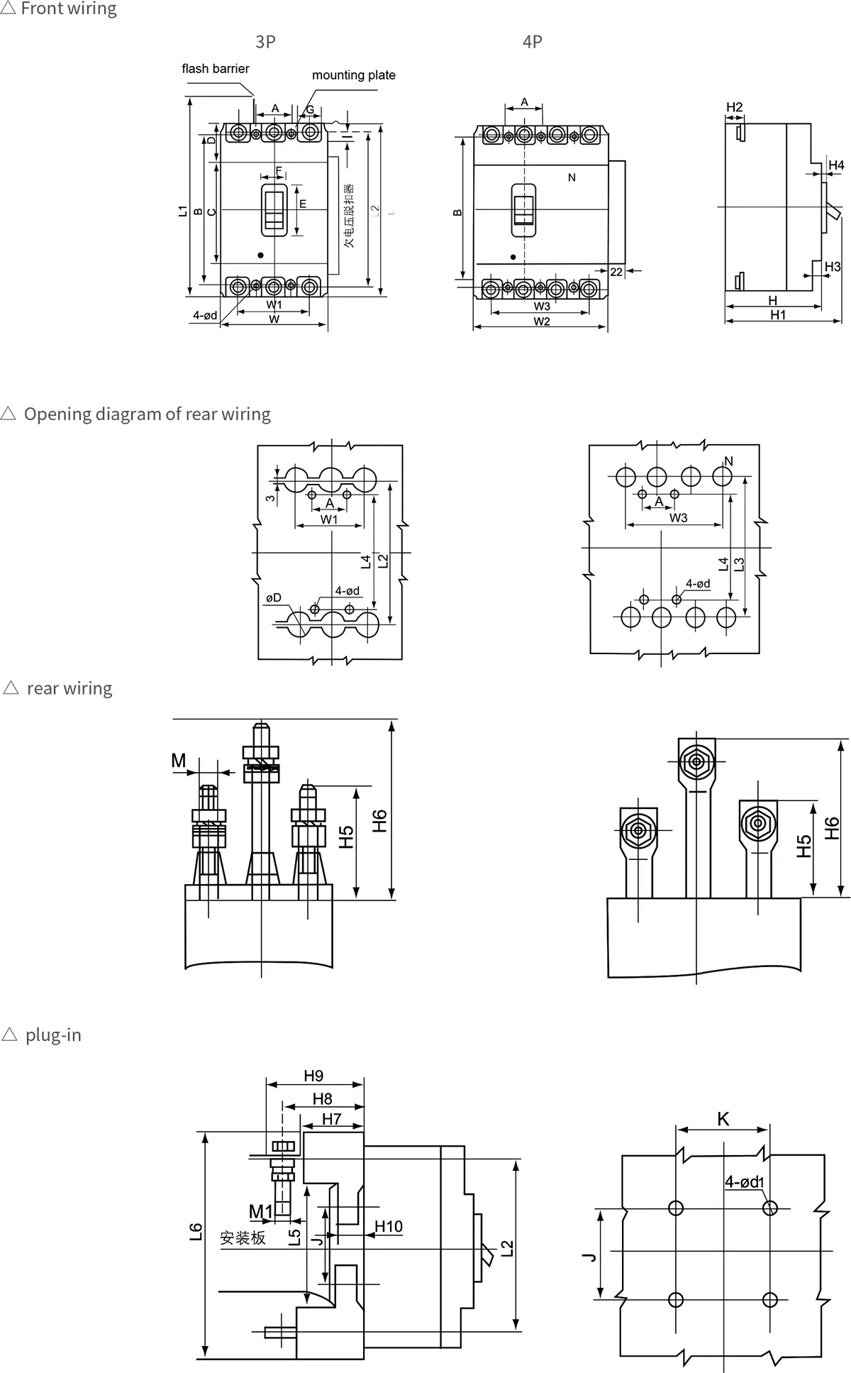
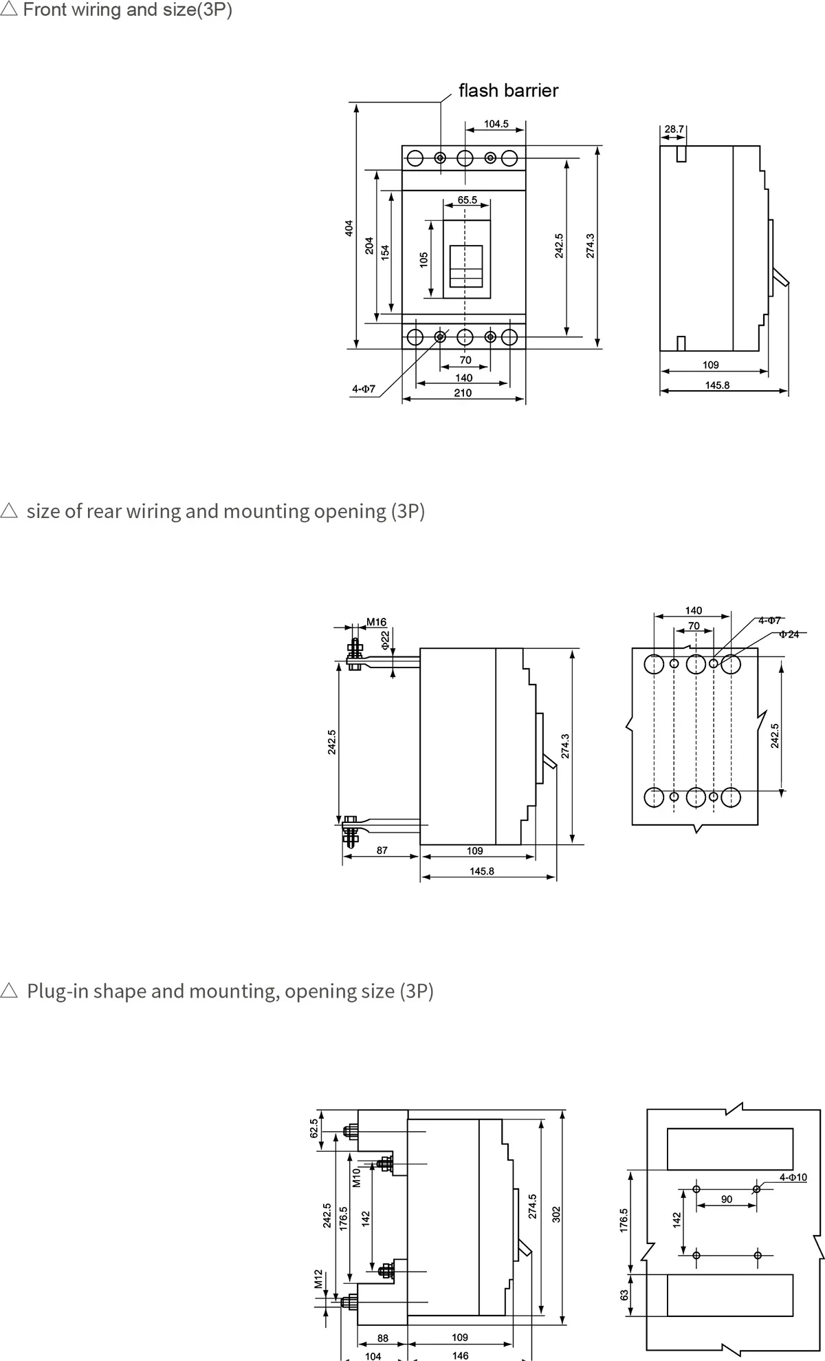
Appearance and installation size
| Model | HKM1 | |||||||
|---|---|---|---|---|---|---|---|---|
| measure | code | Unit(mm) | 63M | 100M/H | 250M/H | 400M/H | 630M/H | 800M/H |
| Front wiring appearance size | W | mm | 78 | 91 | 106 | 148 | 180 | 210 |
| W1 | mm | 50 | 60 | 70 | 96 | 116 | 140 | |
| L | mm | 135 | 150 | 165 | 256 | 270 | 280 | |
| L1 | mm | 154 | 199 | 230 | 356 | 370 | 404 | |
| L2 | mm | 117 | 132 | 144 | 223 | 237 | 242.5 | |
| L7 | mm | 27 | 28 | 37.2 | 66.1 | 63.2 | 63.2 | |
| H | mm | 81 | 86 | 104 | 108.5 | 111.5 | 116.5 | |
| H1 | mm | 98.5 | 104 | 127 | 155 | 160 | 145.8 | |
| H2 | mm | 27.5 | 24 | 24 | 38 | 40 | 28.7 | |
| H3 | mm | 7 | 7 | 4.5 | 8 | 8 | 8 | |
| H4 | mm | 4 | 4 | 3.5 | 6 | 6 | 6 | |
| C | mm | 85 | 88 | 102 | 128 | 134 | 154 | |
| D | mm | 26 | 32.5 | 31.5 | 64.5 | 69.5 | 69.5 | |
| E | mm | 48 | 58 | 58 | 89 | 89 | 105 | |
| F | mm | 22 | 22.5 | 25 | 65 | 65 | 65.5 | |
| G | mm | 14 | 17 | 17.5 | 32.5 | 44.5 | 44.5 | |
| I | mm | 7.5 | 8 | 9 | 12.5 | 13 | 13 | |
| Appearance size of rear wiring | W2 | mm | 103 | 121 | 141 | 196.5 | 238.5 | 238.5 |
| W3 | mm | 75 | 90 | 105 | 144 | 173.5 | 210 | |
| L3 | mm | 116.5 | 132.5 | 144 | 224 | 234.5 | 210 | |
| L4 | mm | 117 | 102.5 | 123 | 194 | 200 | 242.5 | |
| H5 | mm | 25 | 68 | 73 | 66 | 68 | 87 | |
| H6 | mm | 49.5 | 102 | 110 | 118 | 124 | 87 | |
| ∅ D | mm | 6.5 | 24 | 24 | 24 | 24 | 24 | |
| M | mm | M6 | M8 | M10 | M12 | M16 | M16 | |
| L5 | mm | 100 | 92 | 94 | 169 | 170 | 176.5 | |
| L6 | mm | 135 | 168 | 185 | 279 | 299 | 302 | |
| H7 | mm | 27.5 | 38 | 45.5 | 60 | 60 | 88 | |
| Plug‑in profile size | H8 | mm | 36 | 65 | 68.5 | 81.5 | 92 | 88 |
| H9 | mm | 43 | 77 | 86.5 | 105.5 | 112 | 104 | |
| H10 | mm | 8 | 17.5 | 18 | 18.5 | 20 | 20 | |
| J | mm | 60 | 56 | 54 | 129 | 123 | 142 | |
| K | mm | 50.5 | 60 | 70 | 60 | 100 | 90 | |
| ∅ d1 | mm | 5.5 | 6.5 | 6.5 | 8.5 | 8.5 | 10 | |
| M1 | mm | M5 | M8 | M8 | M12 | M12 | M12 | |
| Installation size | A | mm | 25 | 30 | 35 | 44 | 58 | 70 |
| B | mm | 117 | 129 | 126 | 194 | 200 | 204 | |
HKM1-63-630M Appearance and installation size