 Huanghua Group Co., Ltd.
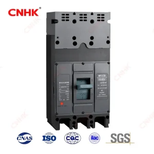
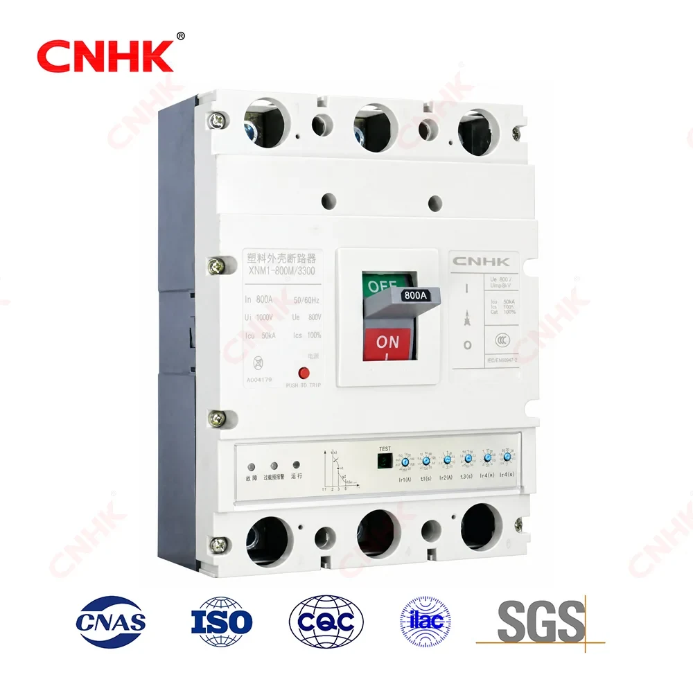
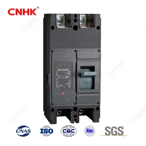
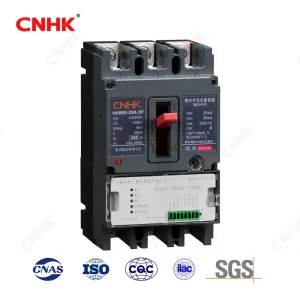
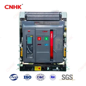
HKM1E Electronic Trip Molded Case Circuit Breaker
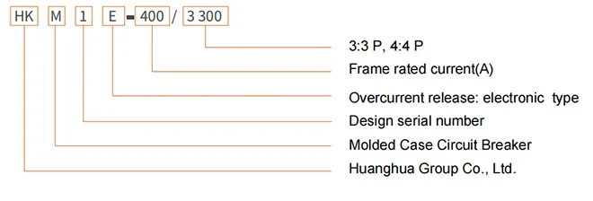
Model and its meaning
Product overview
| General Information | HKM1E series intelligent MCCB is a high-tech product for the 21st century: advanced design, reliable performance, high technical index, attractive appearance, compact size, adopting microelectronics with intelligent overcurrent protection. |
| Key Highlights | Microprocessor-controlled intelligent trip unit; 3-stage protection adjustable on-site via setting knobs
Overload inverse-time + S/C short-time delay + S/C instantaneous, optimally matched to the load Self-powered by CT; reliable operation when three-phase >0.2In or single-phase >0.5In Panel indicators (operation / pre-alarm / overload) + trip test socket for maintenance |
| Main Advantages | Intelligent & adjustable, excellent selective protection High breaking capacity (Icu up to 100kA) Compact, flexible mounting (vertical/horizontal) Complies with IEC 60947-1 & IEC 60947-2 App.F For power distribution and infrequent motor control |
| Typical Applications | Industrial plant power distribution Data centers & commercial building LV distribution Motor circuit protection (infrequent operation) New energy & infrastructure distribution |
| Standards (IEC / GB) | GB/T 14048.1 = IEC 60947-1 GB/T 14048.2 = IEC 60947-2 Pollution degree 3 / Installation category III |
Product Features
-
3-stage intelligent adjustable protection: overload inverse-time, short-circuit short-time delay, short-circuit instantaneous.
-
Adjustable short-circuit characteristics enable clear selective protection with downstream devices in series.
-
Microprocessor-controlled overcurrent release with self-generated power from matching CT.
-
Self-powered: operates reliably when three-phase current >0.2In or single-phase >0.5In.
-
Operation / pre-alarm / overload indicators on the panel for real-time status.
-
On-panel parameter setting via six knobs + trip test through test socket for commissioning & periodic inspection.
-
Basic vertical mounting (supply above, load below); horizontal mounting also allowed.
-
Terminals 1/3/5/N to supply, 2/4/6/N to load; reverse connection not allowed.
-
Rated insulation voltage Ui=1000V; rated impulse withstand voltage Uimp=8kV(125/250) / 12kV(400/800).
-
Ambient -5℃~+40℃; altitude ≤2000m; pollution degree 3; installation category III.
Product Parameters
| Parameter | Value | Description |
| Frame rated current Inm | 125 / 250 / 400 / 800 A | Four frame sizes: 125/250/400/800 |
| Model | HKM1E-125 / -250 / -400 / -800 | Based on frame grade, there are four series models. |
| Rated current In | 32/63/125/250/400/630/800 A | Rated current per frame can be ordered for each frame. |
| Long-delay setting current Ir1 | 16-32 / 32-63 / 63-125 / 100-250 / 160-400 / 250-630 / 315-800 A | Continuously adjustable to match load characteristics |
| Pole | 3P / 4P | Three or four poles are available. |
| Rated insulation voltage Ui | 1000 V | 1000V for all frames |
| Rated impulse withstand voltage Uimp | 8 kV (125/250) ; 12 kV (400/800) | Inm=125/250 is 8kV; 400/800 is 12kV. |
| Rated short-time withstand (kA/1s) | 5 (125) ; 10 (250/400/800) | Short-time withstand |
| Arcing distance | 50/0 mm (125/250) ; 70/70 mm (400/800) | 0 indicates Zero flashover |
| Short-circuit breaking capacity level | M / H | Standard M and High-Segmentation H |
| Rated ultimate S/C breaking Icu | 35/50/65/100 kA (depending on the frame and M/H) | Up to 100kA (H type 250/400/630/800) |
| Rated operating S/C breaking Ics | 25/35/50/65/75 kA (depending on the frame and M/H) | Up to 75kA (H-type 400/800) |
| Applicable supply | AC 50Hz, 400V | AC 50Hz, 400V |
| Rated current range | up to 800A up to 800A | Maximum 800A |
| Trip unit power supply | Self-generated power by CT | Three-phase >0.2In or single-phase >0.5In for reliable operation |
| Protection characteristics | Overload inverse time limit + short circuit short delay + short circuit instantaneous | Three-stage protection |
| Short-time delay setting Isd | 2~12×Ir (32-250A, can be OFF) | Adjustable; disconnect function can be turned off. |
| TSD setting | 0.06 / 0.1 / 0.2 / 0.3 s (can be OFF) | Fixed delay levels Definite time steps |
| Instantaneous setting Ii | 4~14×Ir (depending on In, can be OFF) | Classified by rated current. Adjustable by In |
| Operating temperature | -5℃ ~ +40℃ | Ambient air temperature |
| Altitude / Pollution / Inst. cat. | ≤2000m / Grade 3 / Category III (Cat.III) | Normal operating conditions |
| Indication | Operation/Warning/Overload Indicator | Operation / pre-alarm / overload indicators |
| Mounting | Vertical (on the power supply, under the load) or horizontal | Vertical (supply up) or horizontal |
| Standards | IEC 60947-1 / IEC 60947-2 + App.F (GB/T 14048.1/.2) | IEC + Chinese national standards, including Appendix F on electronic overcurrent. |
Installation considerations
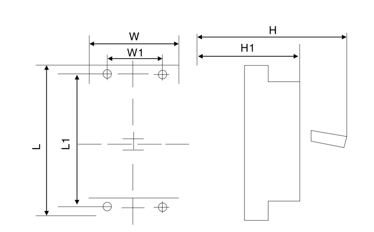
| HKM1E‑125 | HKM1E‑250 | HKM1E‑400 | HKM1E‑800 | ||||||
| 3 | 4 | 3 | 4 | 3 | 4 | 3 | 4 | ||
| Overall dimensions | L | 150 | 150 | 165 | 165 | 257 | 257 | 280 | 280 |
| W | 92 | 122 | 107 | 142 | 150 | 198 | 210 | 280 | |
| H1 | 92 | 90 | 92 | 92 | 107.5 | 107.5 | 116 | 116 | |
| H | 110 | 110 | 110 | 110 | 150 | 150 | 155 | 155 | |
| Installation dimensions | W1 | 30 | 60 | 35 | 70 | 44 | 94 | 70 | 140 |
| L1 | 129 | 129 | 126 | 126 | 94 | 194 | 243 | 243 | |